![]()
Steering, Wheels, and Suspension
While the steering and suspension parts didn't look bad superficially, they hadn't had any attention for a long time. Replacing or rebuilding all shocks, bearings, and bushings gives any car a solid, new feel, so all that was in order. The wheels also were a concern. I had hoped to reuse the existing disk wheels, but they were not in good enough condition.
Click on any picture to see a larger version in a new window.
Contents
- Front Suspension Disassembly
- Front Suspension-Arm Brackets
- Suspension Arms
- Front Suspension Assembly
- Fulcrum Pin Orientation
- Hubs and Steering Arms
- Steering Rack
- Steering Column
- Rear Springs
- Rear Suspension
- Tires and Wheels
- Wheel Alignment
Front Suspension Disassembly
With the brake calipers removed for restoration, I was ready to remove the front-suspension components. I started by removing and separating the disk and hub, then removing and inspecting the bearings. I didn't take a lot of pictures of the disassembly, as it was very messy, and I didn't want to handle the camera with dirty hands. The disassembly was, in any case, straightforward.
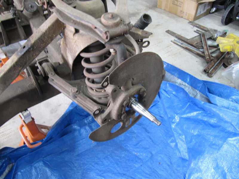
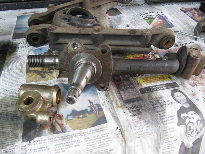
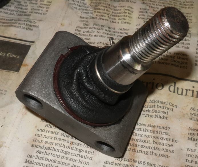
Below is the right-side spindle. It looked good, fortunately.
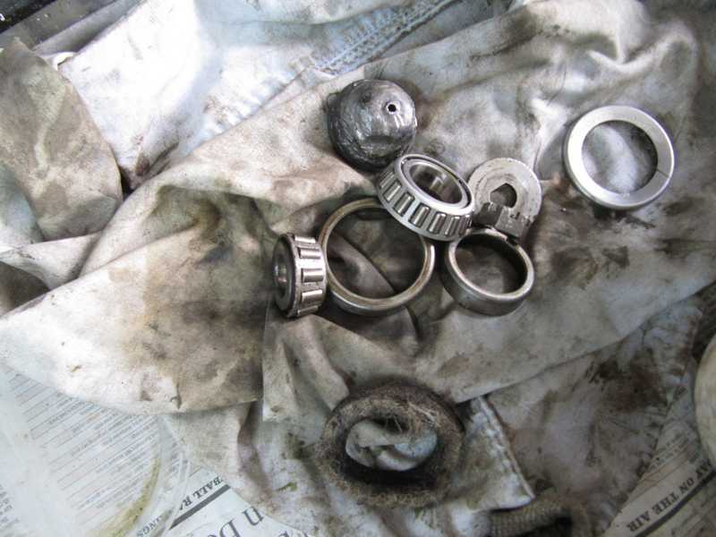
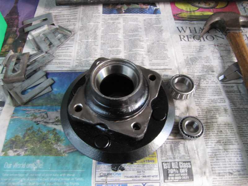
The cleaned right-side hub is shown below. It had about a half can of grease in it, so cleaning it was a messy job.
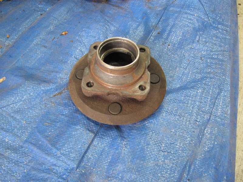
The outer bearing simply falls out of the hub when it is removed; the inner bearing drops out when the felt seal is removed. The races are more difficult. The shop manual says only that they should be hammered out with a drift. There are notches on the inside of the hub, which accommodate the blade of a large screwdriver; I placed a screwdriver, gave it a few whacks with a good-sized hammer, and the races came out fairly easily.
The bearings were not too bad, but they were old, so I decided to replace them. One bearing actually had rust on its cage--how does that happen, when the bearing is embedded in grease?
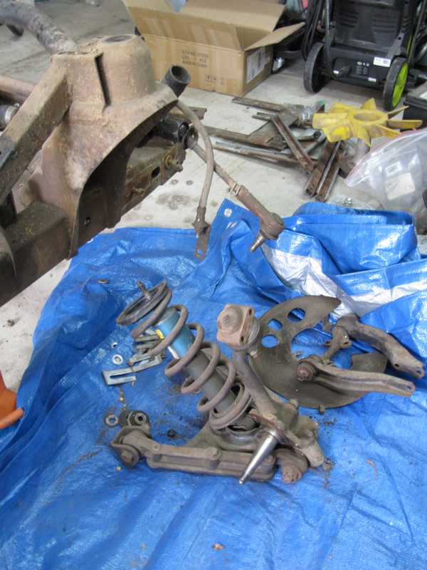
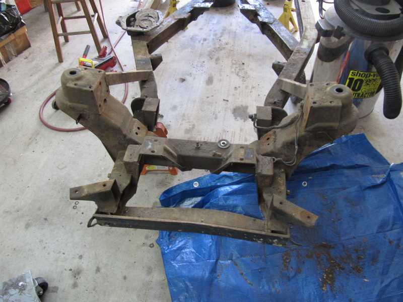
The right front wishbones, spring, and shock absorber came out as a unit. I disassembled them partially, just enough for convenient storage. I removed and cleaned the trunnion so I could evaluate its condition; fortunately, it was fine. (I later determined that the left-side trunnion was OK, too.) With the removal of the left-side suspension, the steering rack, and the engine mounts, the front of the frame was finally empty. Removing those parts was easy; it involved only unbolting them.
I have since learned that the vertical link (the part that swivels) is often bent. I didn't check it, but it seems that I lucked out; I encountered no problems in the wheel alignment, and the steering in the completed car is fine. If I ever do this again, I'll check the links carefully.
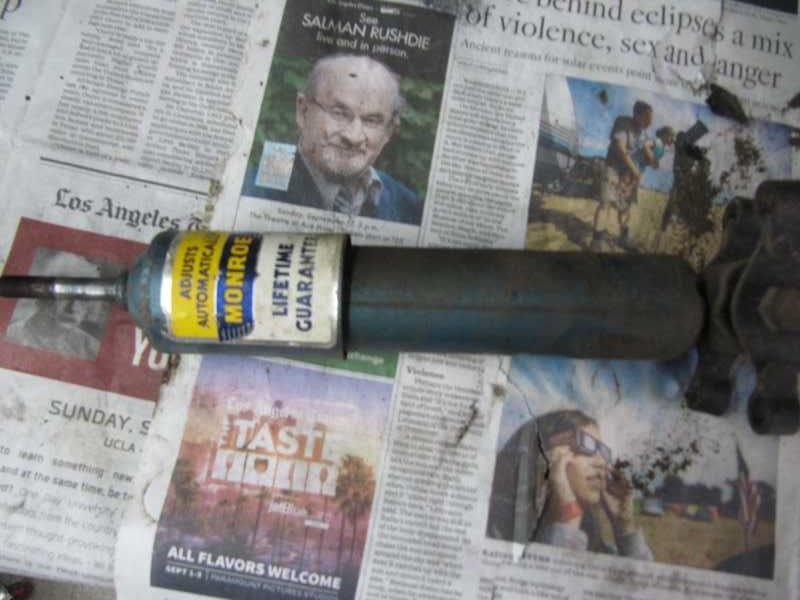
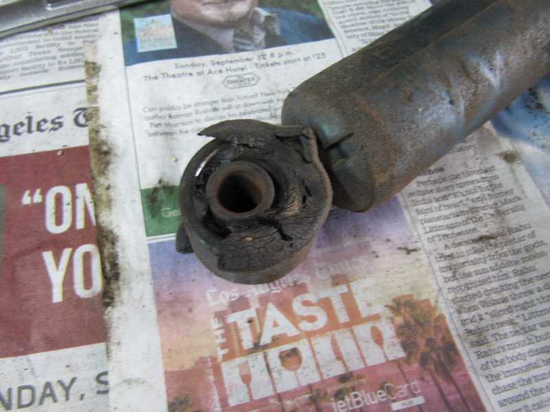
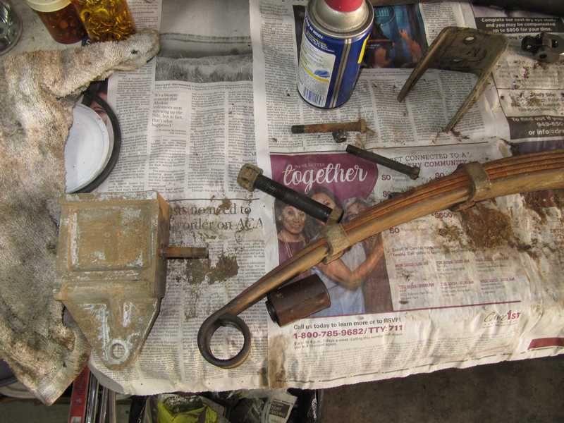
Monroe was a big name in shock absorbers in the car's era. The company is still around, but, no great surprise, they don't make TR4A shocks any more. I suspect these were installed no later than 1980. The lower bushing was totally shredded; it probably made disturbing clunks when the car hit a bump. I replaced these shocks were with Konis, which are just a bit more upmarket.
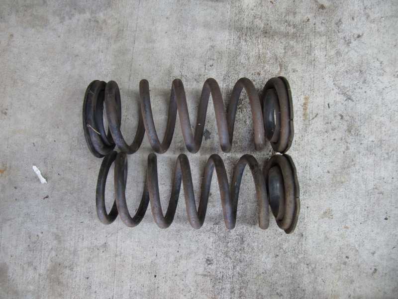
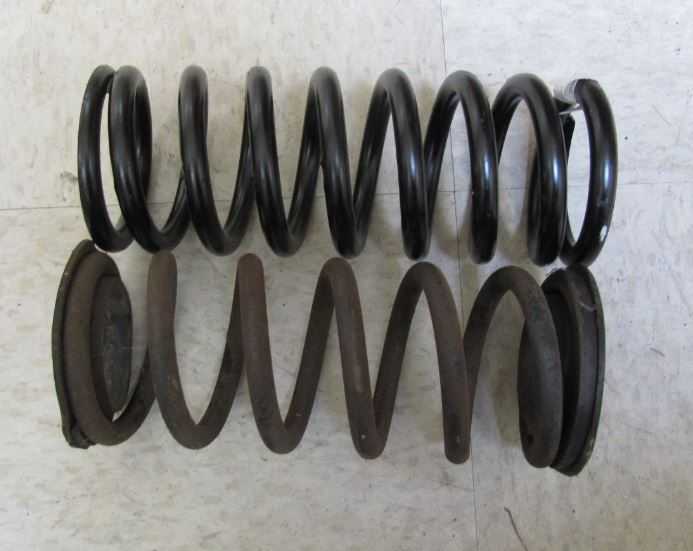
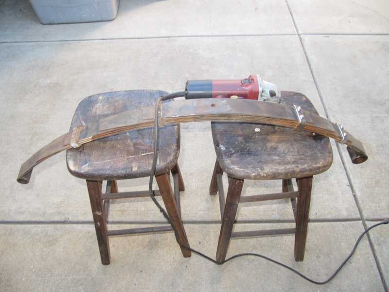
One spring has sagged; that's a good excuse to replace both. The second picture compares the longer of the old springs to a new one. They are quite different. The new one has more turns, but the wire diameter is larger; presumably, it has the same spring rate. Let's take a look.
The Bosch Automotive Handbook (8th ed., p. 244) gives an expression for the spring rate of a coil spring. For the same material and major diameter (i.e., diameter of the helix), the rate varies as d^4/n, where d is the minor diameter (i.e., diameter of the wire) and n is the number of turns. For the old spring, d = 0.480 inches and for the new one, d = 0.525. The old spring has 5 turns, while the new one has 7. For the new spring, d^4/n = 0.01085 and for the old one, 0.01062. This is a difference of only 2%, which is not significant.
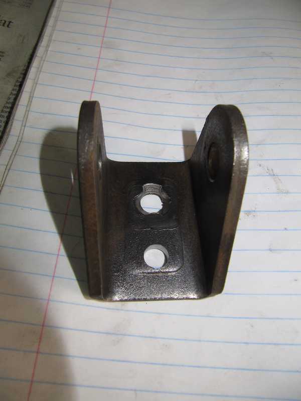
Front Suspension Arm Brackets
Strengthening the lower A-arm mounting brackets in a TR4A is essential, as they are simply too weak. This involves modifications to the frame mounts (described in the Frame page), as well as the A-arm brackets themselves. The modifications involve adding a second mounting stud; additionally, to accommodate a thick, square back-up washer, both studs must have greater protrusion than their original one-inch length. So, both studs had to be replaced.
Because of the small clearance between the bracket and A-arm, the upper (original) stud is a special type, something like a flat-head bolt with an especially large head. It is welded in place. To remove it, I cut off the stud, machined off the head, then pressed out the remains.
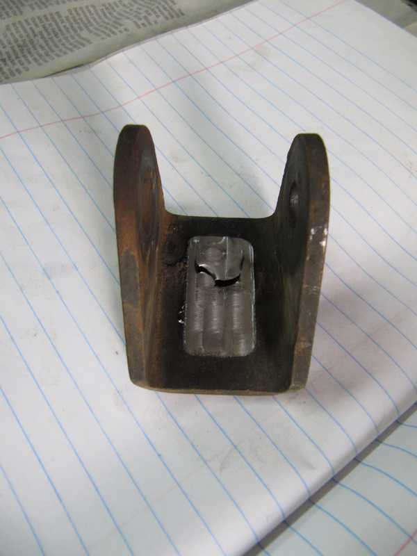
I was left with a tapered hole, plus the remains of the welds. Some of that taper was filled when I welded the new bolt into place.
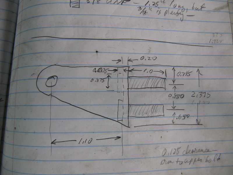
I measured the existing bracket and sketched it into my project notebook. The 1.0-inch length is that of the original stud; I used 1.5-inch bolts both places, so the protrusion would be 1.3 inches. The location of the lower stud was found by measuring the square back-up washer that reinforces the frame bracket.
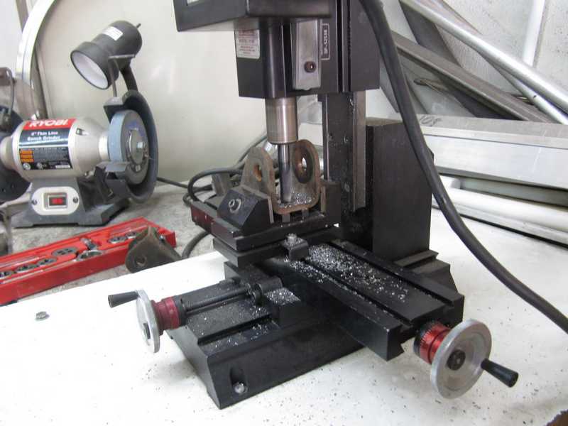
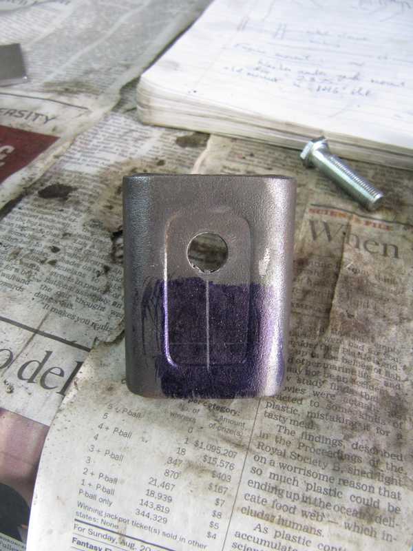
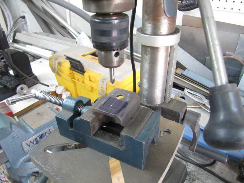
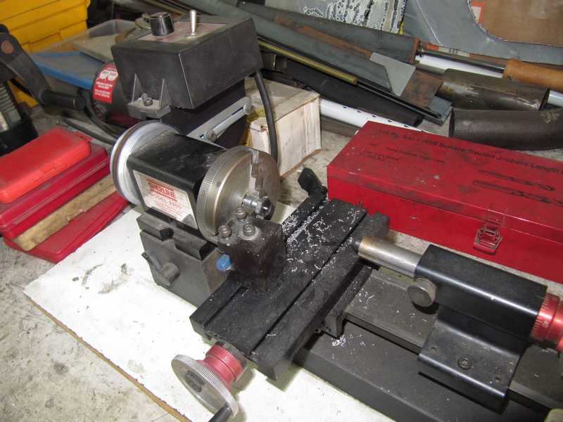
Drilling large holes accurately in steel can be tricky, as large drill bits wander a lot. Drilling a guide hole is essential. I first scribed the new hole location onto the bracket, center-punched it, and enlarged the dimple with a spotting drill. Using carbide tools, I then drilled the 1/8-inch guide hole and finally the 3/8-inch hole. Carbide tools are not essential for drilling mild steel, but they cut faster than high-speed steel and create a cleaner hole.
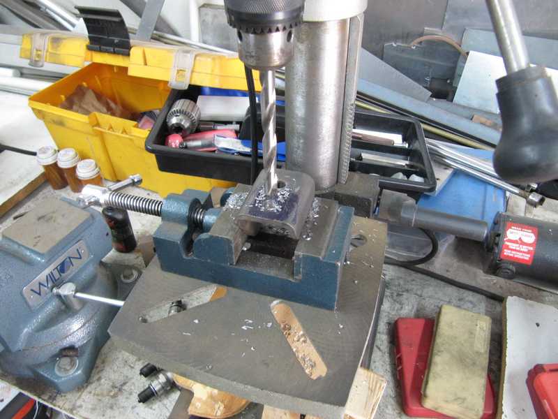
The result was a clean, accurate hole.
Now for the studs, which consisted of 3/8 x 1.5 inch UNF bolts. The head of the lower bolt cleared the A-arm easily, but the upper bolt's head was too thick. I thinned those bolts' heads in a lathe to 0.20 inches and checked them for fit.
I used nuts to hold the bolts' heads tight against the bracket for welding. To make sure the pairs of bolts were parallel, I attached a square back-up washer to each. A few tack welds held the bolts stationary in the brackets.
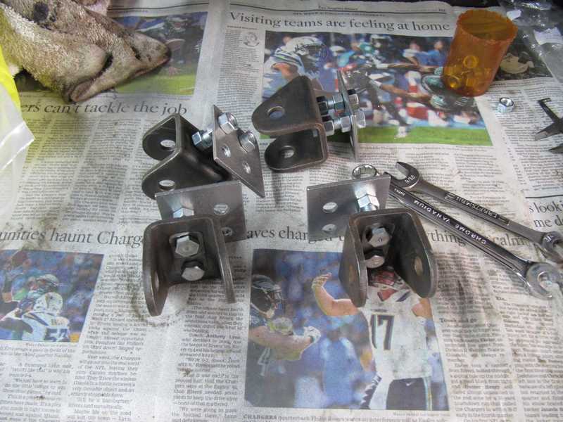
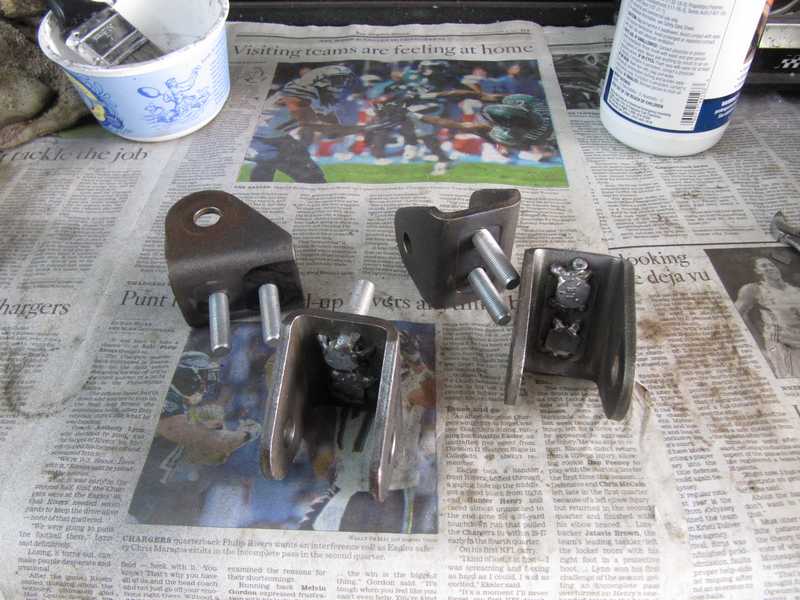
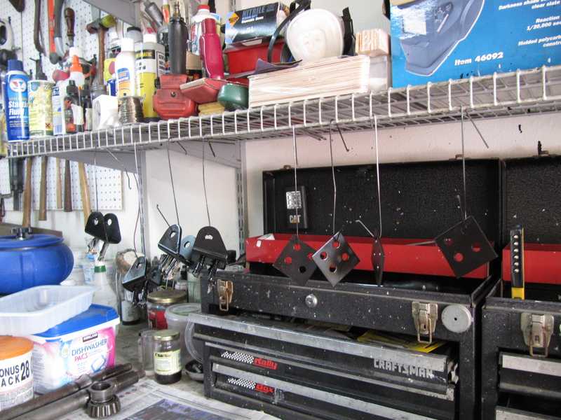
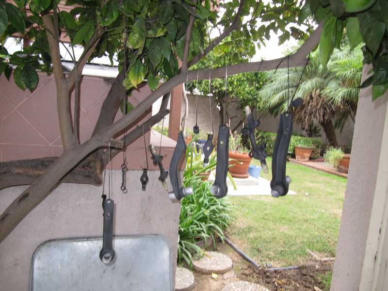
Primed and painted, the brackets were hung over my workbench to dry.
Suspension Arms
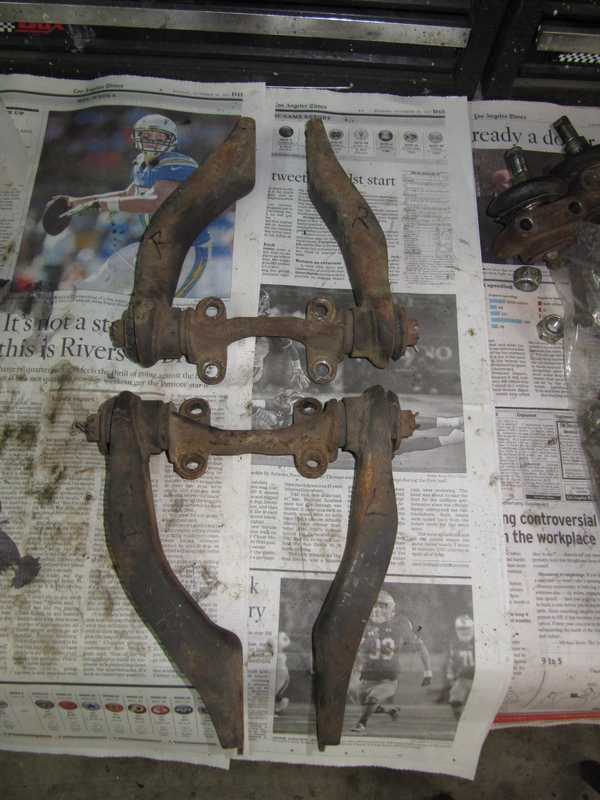
Restoring the front suspension arms was straightforward. The arms were in rough shape but had no bends or other damage. Unsurprisingly, the ball joints and the bushings needed replacement. Below are the upper arms as they came off the car.
As with other parts, I washed them in solvent and then detergent, wire-brushed and sanded them to remove any remaining rust and dirt, and primed them. For small, simple parts like this, I like to use Rustoleum gray automotive primer in a spray can.
The lower arms and spring pan were similarly restored. Most of the brown stuff is just dirt, not rust.
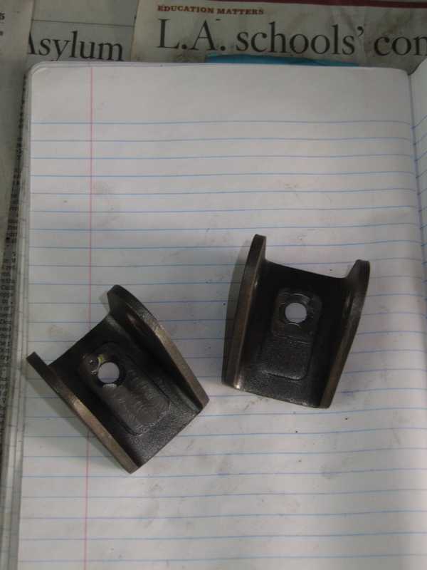
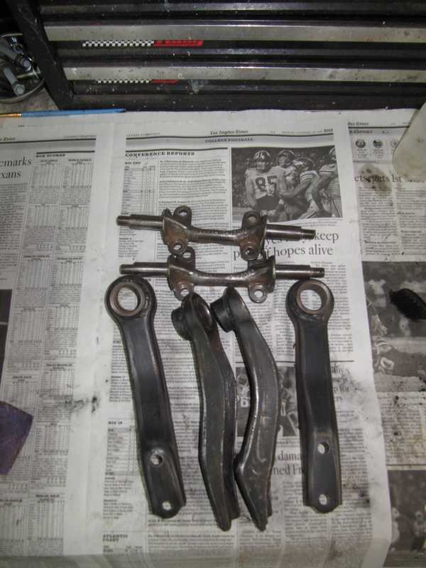
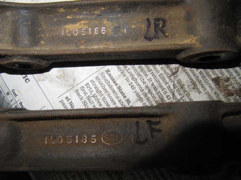
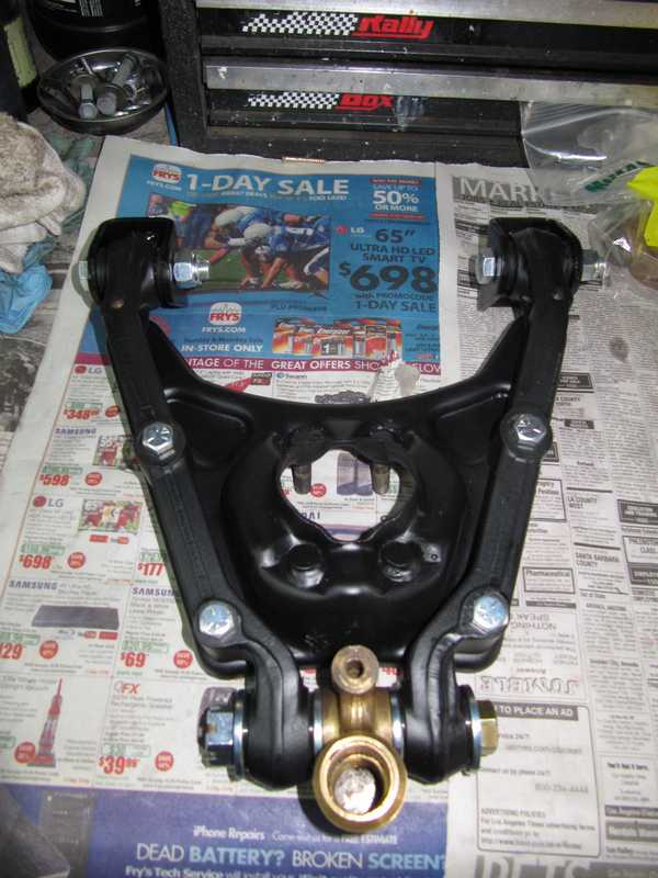
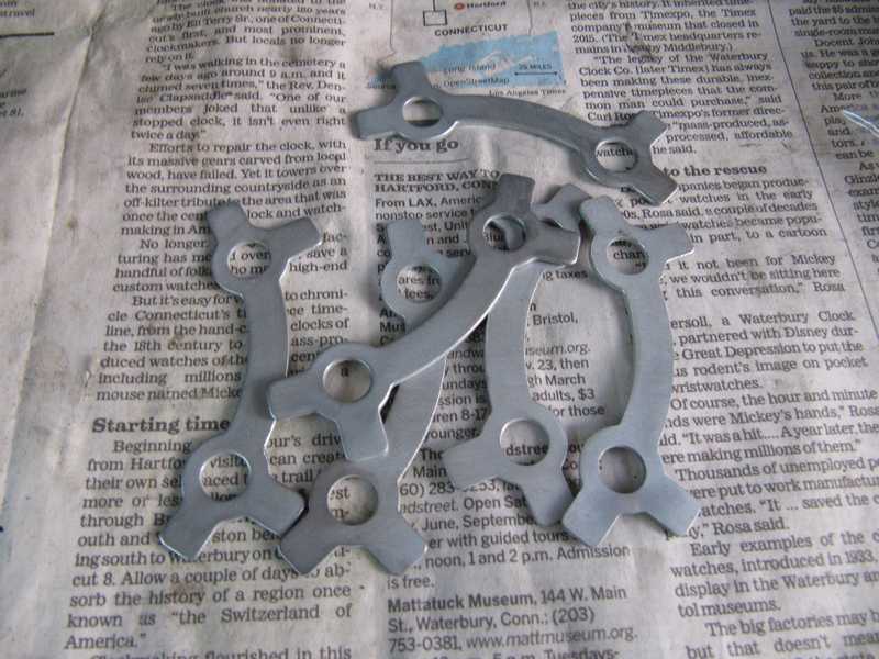
There seems to be a lot of confusion about making sure that the lower A-arms on TRs are installed correctly. The two arms on each side have different part numbers; below are the left rear and left front arms, with the part numbers easily visible. The one with the part number ending in 86 is the left rear and 85 is the left front; on the right side, it is opposite: 86 is the front and 85 is the rear. This makes the completed arms mirror images of each other. They really can't be installed the wrong way unintentionally; if they are somehow installed wrong, something eventually just won't fit.
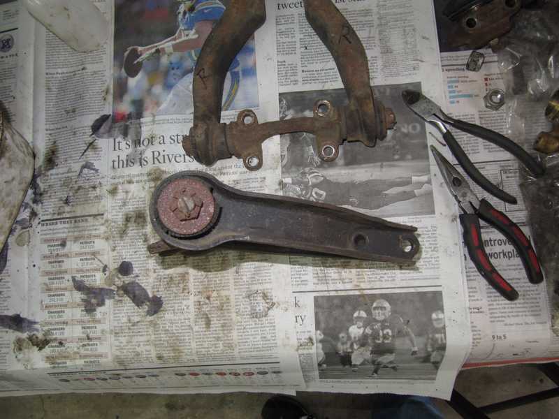
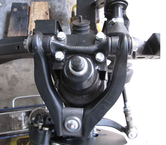
While we're at it, there is also some confusion about the upper wishbones. In early TRs, the two arms of the upper wishbone are identical, but in most TR4s and all TR4As, the arms are different. On both sides, the longer arm goes in the front, as shown in the picture below (front is to the right); this moves the ball joint a little to the rear, providing about 3 degrees of caster. Each of the longer arms is marked R on one side and L on the other. As long as the R is up on the right side, and L on the left, the assembly is correct.
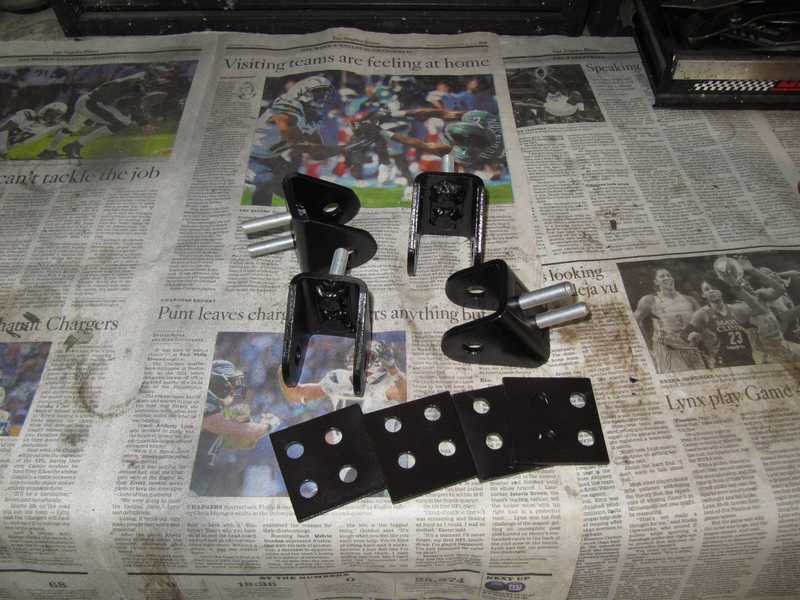
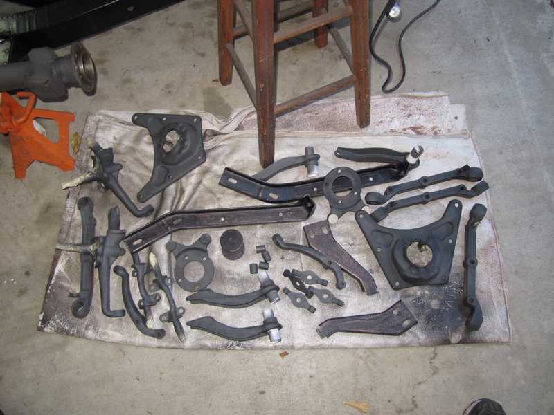
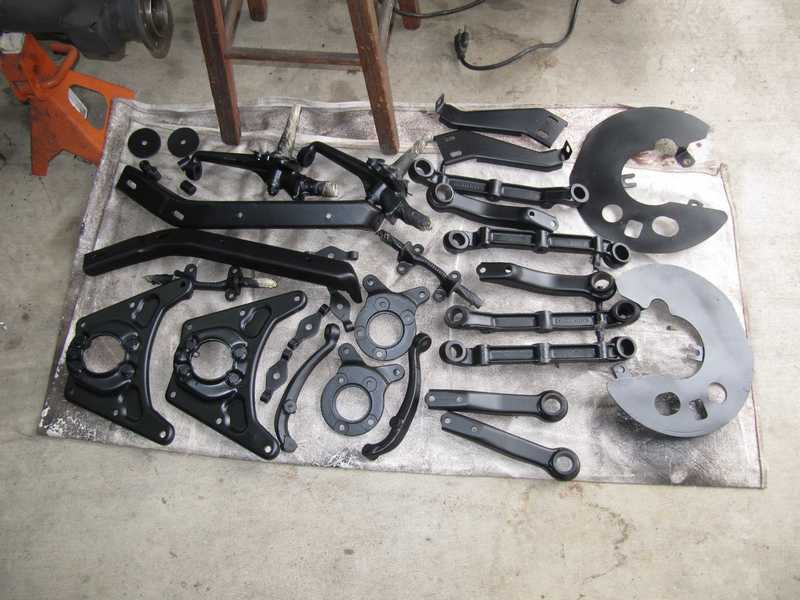
The suspension parts were cleaned, wire brushed, masked, primed, and painted as a single batch, along with some other bits, in the usual manner. I applied the same semigloss Rustoleum that I used for the frame. The first picture below shows the primed parts; the second two, the painted parts drying. Some of the bumper-support pieces appear in the pictures; I painted them at the same time.
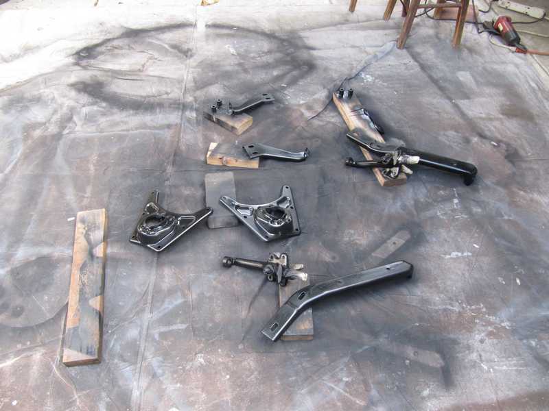
The painted parts, ready for assembly.
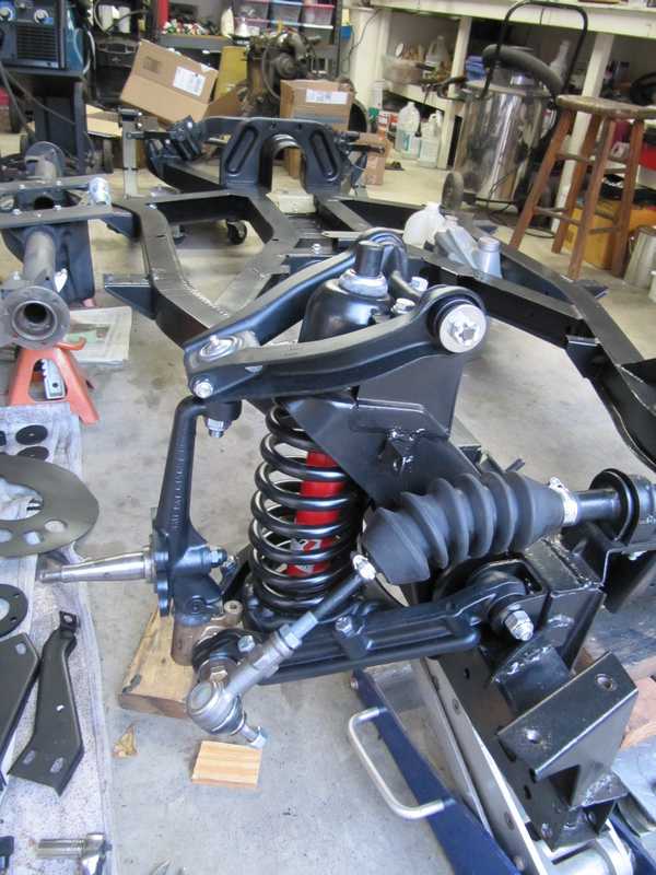
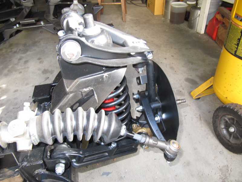
Front Suspension Assembly
Each side of the front suspension has to go together in a particular order: first the upper and lower arms, then the spring and vertical link, and finally the shocks. Once those are done, the hubs and brake components can be installed. Although I installed the steering rack before the suspension bits, it's probably better to install it afterwards.
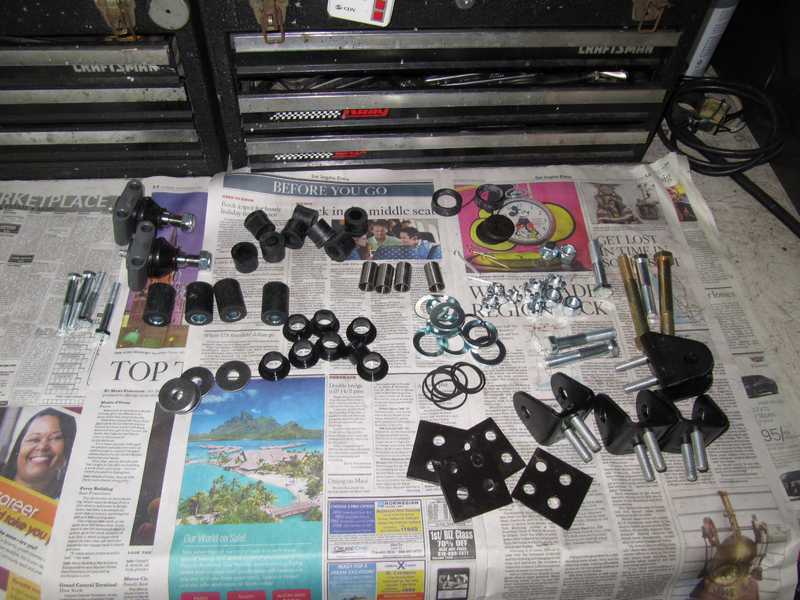
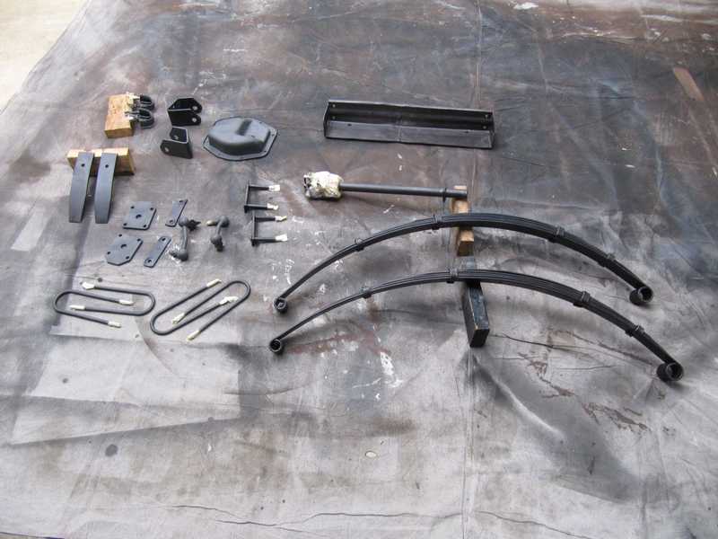
The kit for the front suspension is shown below, along with the restored mounting brackets and new ball joints. I'm glad I kept good notes as I disassembled the car; if I hadn't, it would have been be pretty hard to figure out where everything went. The shop manual was not much help, as it is much better for the TR4 suspension than the TR4A, and even then, it has errors. Beyond that, everything fit well and the assembly was straightforward. (For reference, the rubber bushings in the upper part of the picture, along with the four galvanized washers, are for the upper A arms, the four thick slugs with internal metal sleeves are for the inner joints of the lower arms, and the rest is for the trunnions. The locations of bolts and nuts should be obvious from their sizes and numbers. The trunnion assembly is a puzzle, but on p. 4-118, the shop manual has a useful figure.)
Below are the assembled lower arms and spring pan. The arm and pan assemblies by themselves are identical and can be used on either side of the car, but the trunnions are not identical (the left side has a left-handed thread, and the right side a right), and the bolts in the inner joints must be oriented so the nuts are toward the front of the car. Below is the right-side, lower-arm assembly.
The springs cannot be installed with the spring pan in place unless an appropriate spring compressor is available. Most available compressors are designed for larger springs (as was mine, I later discovered) and won't fit the TR springs. Thus, it is necessary to remove the pan from the arms to install the springs. Installing it temporarily, at this point, is still a good idea, as it allows correct alignment of the arms with the pan and bushings. If that was not done, the bolt holes in the arms and pan probably would not line up correctly when the parts were assembled.
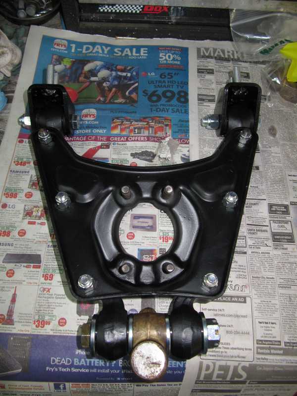
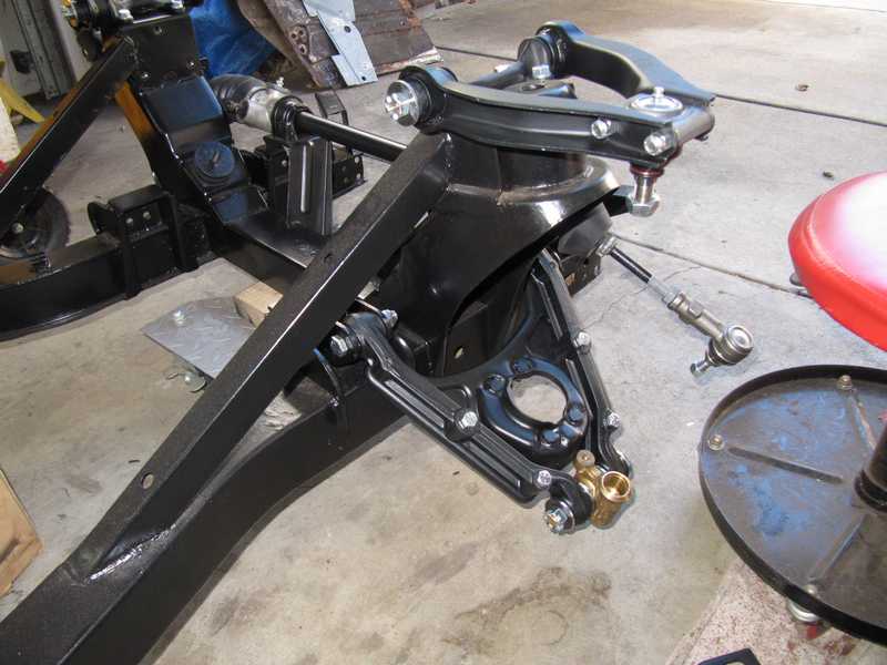
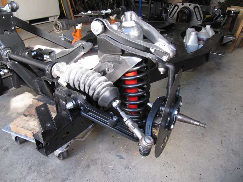
Below, both the upper and lower arms have been installed. Tightening the bolts that squash the rubber bushings generally must be delayed until full weight is on the suspension, so the bushings are tightened in their equilibrium positions. One exception is the upper-arm bushings, which must be tightened with the arms centered in the bushings. This must be done before the ball joint is installed, or it won't be possible to center them properly. Once the bushings are compressed, they can be loosened a bit to move the arm around as necessary; say, for installing the vertical link.
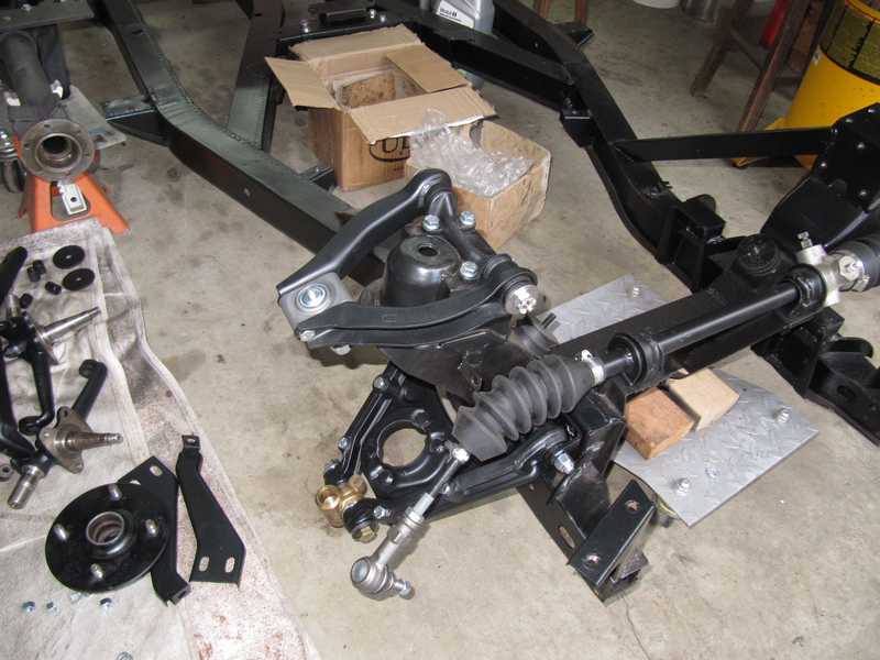
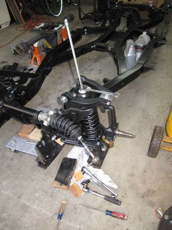
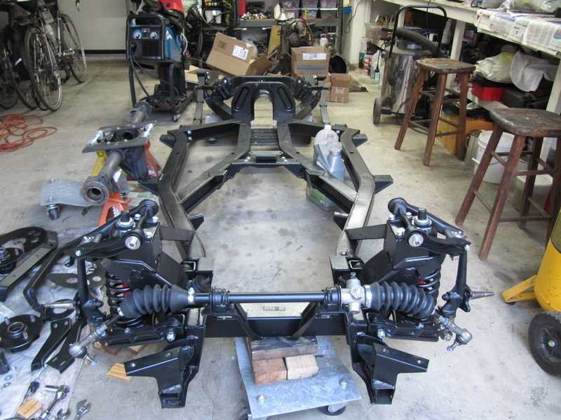
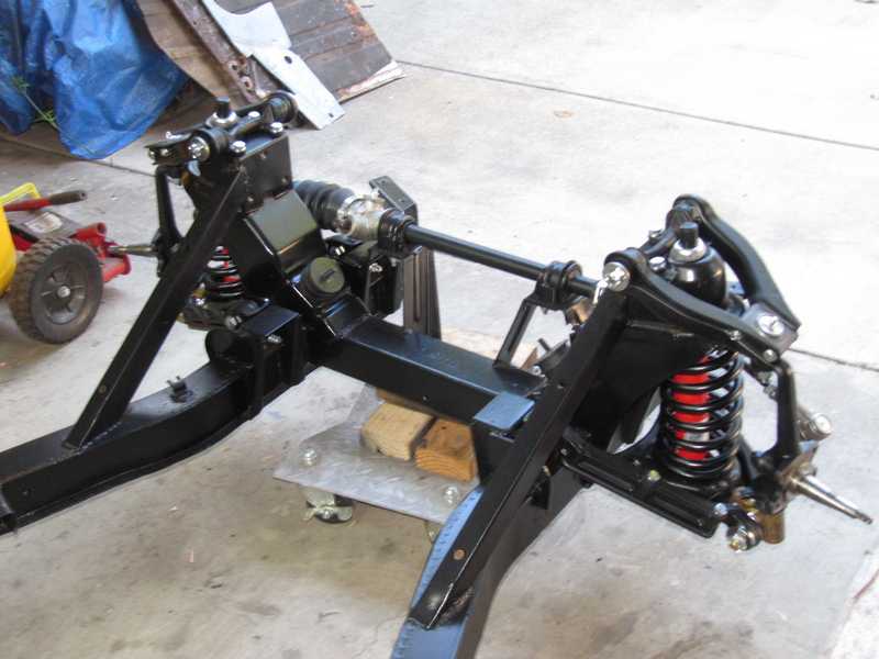
These pictures show the problem with installing the steering rack before the suspension: it just gets in the freakin' way!
Here's the spring compressor. If I were to do this again, I'd make some changes in it: 1/2 or 5/8-inch fine-threaded rod, instead of the 3/8, and I'd use a plate that was drilled to fit over the shock-mounting studs. Those changes would make the tool stronger and would keep the rod located in the center of the spring; I had some problems with the lower piece slipping to the side. The second picture below shows the spring compressor in use. Whatever its faults, it did the job.
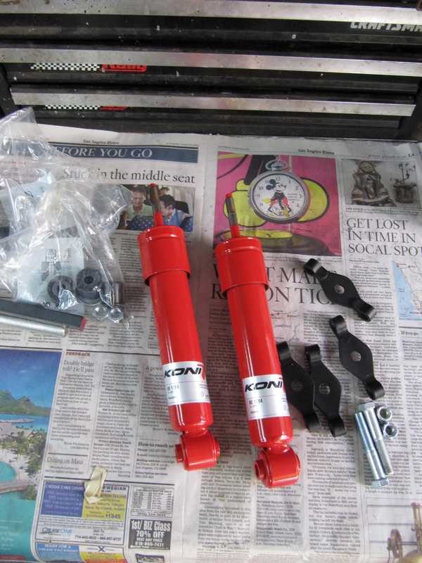
I installed a set of Koni shock absorbers. There are a number of options for TR4/4a shocks, but Konis are certainly a safe choice.
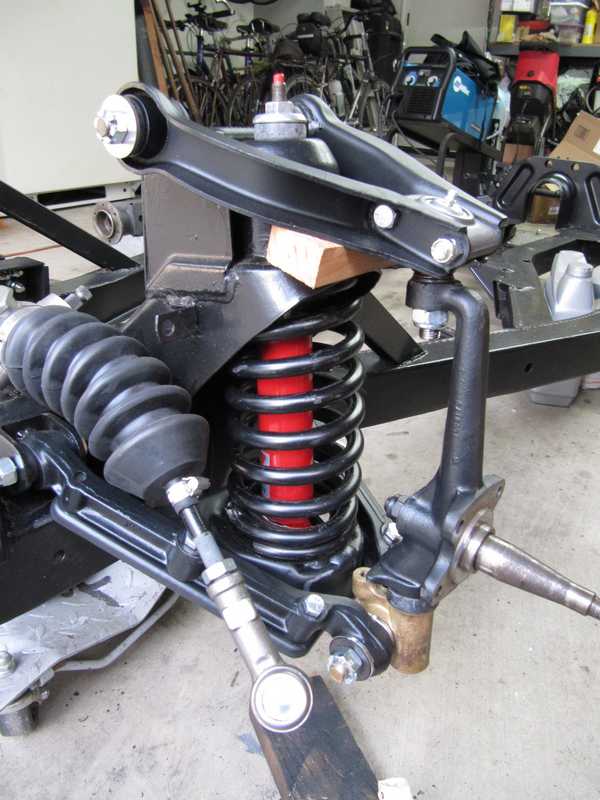
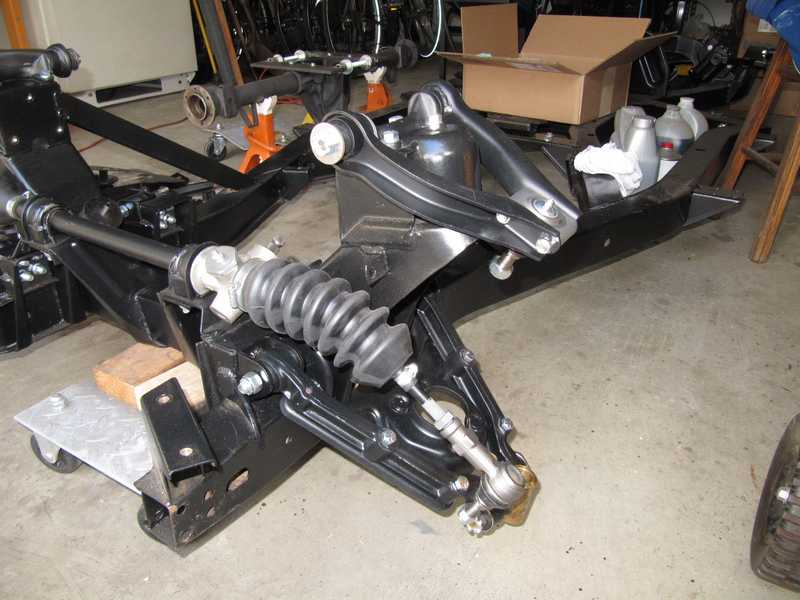
I assembled the right side in the same manner. The suspension assemblies are now complete.
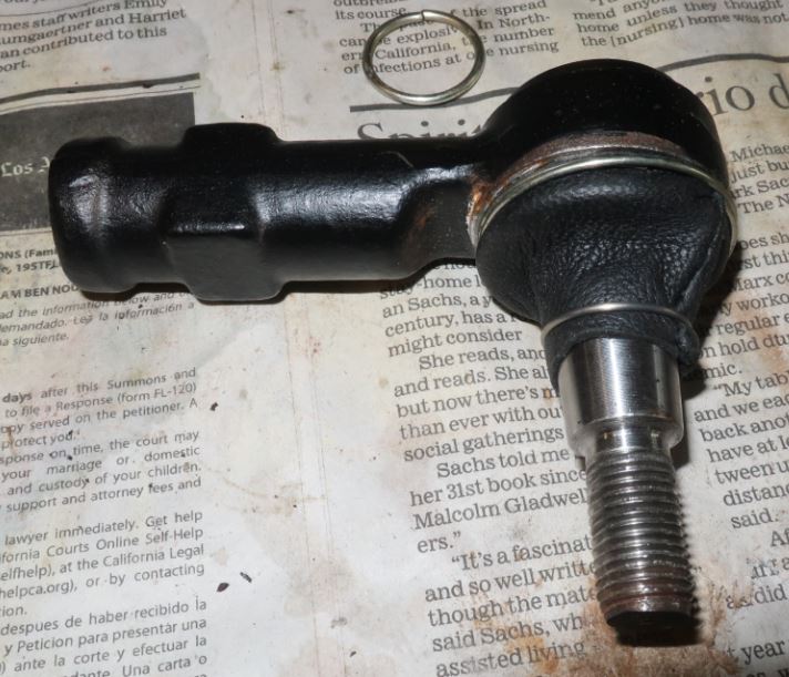
Ball Joint and Tie-Rod Boots
Two years later, here's what the ball-joint boots looked like. The tie rods were just as bad.
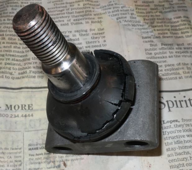
Admittedly, it sat for some time in an extreme position, but I still think it should not have deteriorated so badly in such a short time. The tie-rod ends were worse; they cracked in less than a year. I replaced the boots with generic ones, and a year later, they again were goners. Even two spares, which were stored in a small plastic bag among my parts, had started to crack!
The rubber in car parts today is unmitigated crap. It astonishes me that the manufacturers can keep pushing this stuff and pretend that they don't know how bad it is.
So, what to do? getting new joints is not an option; The same thing will happen to them. Generic replacement boots made of flexible polyurethane possibly are a good option, but I couldn't find any in a workable size. Silicone replacement boots also exist, but they must be ordered from overseas and I don't know if they are any better. Rubber generic replacements are sure to be as bad as originals.
Here's my solution: leather. Leather is flexible, grease resistant, and tough. Water resistance may not be as good, but it still should be adequate, and this is, after all, southern California. Some of the original TR4 seals were, in fact, leather; examples are the oil seal in the rear-axle tube and the differential's pinion seal. I made leather boots out of the same thin, flexible leather I used for the gearshift boot. I reused the ball joints' larger spring clips, but the smaller clips didn't fit well; for those, I used soft, stainless-steel wire.
We'll see how this works. At its worst, it can't be worse than the rubber.
Fulcrum Pin Orientation
There is quite a bit of confusion in TR circles about the orientation of the fulcrum pin for the upper suspension arms. The orientation matters, because the axis of the pivot is not centered between the mounting holes; it is 1/8 inch away from that center.
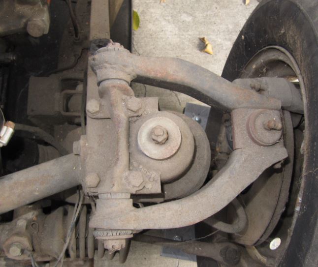
The pin has a bow in it, which seems to be designed to provide clearance around the shock tower. When I took the car apart, though, I was surprised to see it oriented the other way, with the bow extending outward (first picture, below). I assumed that this orientation, however strange, was the original one, so I copied it when I reassembled the front suspension arms.
Then, after finishing the suspension, I was surprised to notice a figure in the shop manual, reproduced below, which has it oriented the other way. This figure is specifically for the TR4A. Before changing everything, however, I did some research.
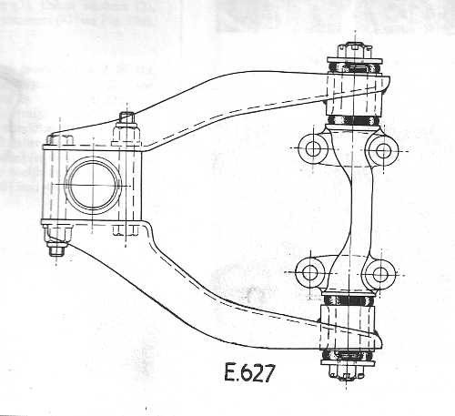
It turns out that on earlier TRs, the fulcrum pin originally was oriented as expected, with the bow extending inward. For the TR4A, and possibly some TR4s, the fulcrum pin was reversed. Roger Williams' book on TR restoration (p. 138) and other sources agree on this; on-line pictures of the TR4A and later suspensions also show the pin oriented with the bow as in the photos, not as in the drawing. Although it seems unlikely that the shop-manual figure would be incorrect, the weight of evidence suggests that it is. I have to conclude that the orientation I've used is the correct one for my TR4A.
I calculate that turning the pin around would make the camber about 1 degree more negative. It's not unlikely that some cars, perhaps for racing, have it purposely reversed (i.e., the bow extending inward, as in the shop-manual figure) in order to achieve a greater camber. That might confuse the issue further.
Hubs and Steering Arms
Installing the brake-caliper plates, backup plates, and steering arms is straightforward. I'm glad that I took notes as I disassembled these parts; the four bolts for the caliper plate are all different sizes. (For the record, the top front is 3 1/2 inches long; top rear is 3 inches; bottom front is 1 3/8 inches, but a 1 1/2-inch bolt is fine; bottom rear is 3/4 inches long, but 1 inch is OK. All are 3/8 UNF.)
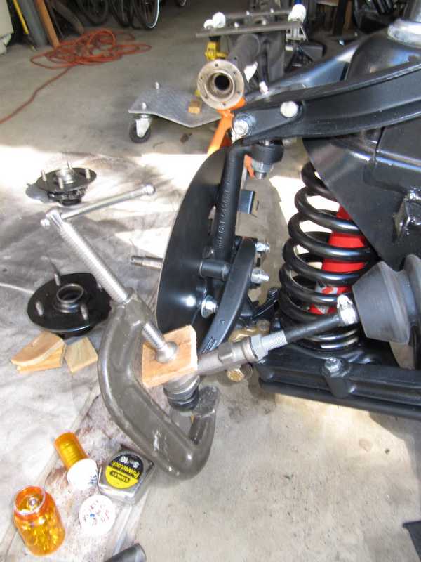
There's a special place in hell for the guy who decided that we must use nyloc nuts on the ball joints and tie-rod ends. There is no way to hold the threaded part while screwing on the nut, so it just rotates. My solution was to press the taper into the mating piece and to hold it with a C-clamp. Not elegant, but it worked. Later, I realized that there is a much easier way to do this: first, tighten the taper with an ordinary nut, then, when the joint is tight, remove the nut and install the nyloc. Duh!
Also--I suspect that the brother-in-law of the guy who chose fasteners for this car owned a business that made nyloc nuts. They are used throughout, often in places where they simply are not necessary. Nyloc nuts are pretty good at preventing loosening under cyclic lateral force, better than an ordinary torqued joint, but in most places they simply aren't needed. Since they are the specified fasteners, however, I still used them. Seemed silly, though.
And, while I'm ranting, I am more than a little skeptical of the locking plates used in many places, including the brake-caliper plate. All the forces to which a fastener is exposed are much greater than the strength of the plates' tabs, so I doubt that they provide much protection against a bolt coming loose. Furthermore, the steel used for the locking plates is soft, necessary for bendable tabs, but that leads to eventual compression and loss of axial tension in the bolt. I've seen them used to hold adjusting nuts that are not torqued (e.g., in old-style clutch pressure plates), where the nut is not subject to much force, but they still fail regularly. Again, since they are specified, I installed them, but I have no confidence in them. I torque everything well and use a thread locker where warranted.
The plates in the car and the ones I purchased were not galvanized. The ones removed from the car were predictably rusty, and the new ones had already started to rust. I cleaned off the rust and galvanized them myself; example below. (Those in the picture are for the rear; I installed the ones for the caliper plate before I thought to photograph them.)
Once the car was together, I found that the differential setup was faulty, and I had to pull the rear axle and redo it. When it went back together, I dispensed with the lock plates and used Belleville washers. Bellevilles are spring washers with a corrugated surface that gives good resistance to loosening.
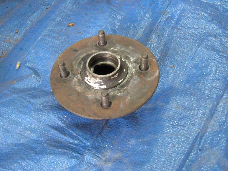
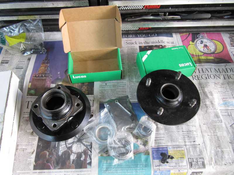
Below are the cleaned and painted hubs, along with the Lucas bearing and seal kits. The hub must be fitted to the spindle before the bearings are greased or the seal is installed; this is necessary to get the right end float. The amount of grease in the packet that comes in the kit is really not enough; I used most of a tube of wheel-bearing grease for the two hubs.
First step is to press both outer bearing races into the hub.
At this point, I discovered that I had mislaid one castle nut and its associated "D" washer. The Law of the Innate Perversity of Everyday Life assured me that I would find it shortly after buying or making new ones. So, I made a new castle nut from an ordinary 1/2-inch UNF nut, milling the slots with a 1/8-inch carbide end mill and machining the opposite surface flat, like the original nut. To make the D washer, I partially welded the hole in a large, 1/2-inch washer, then ground and filed it to size. (Still looking for that damned nut and washer, though!)
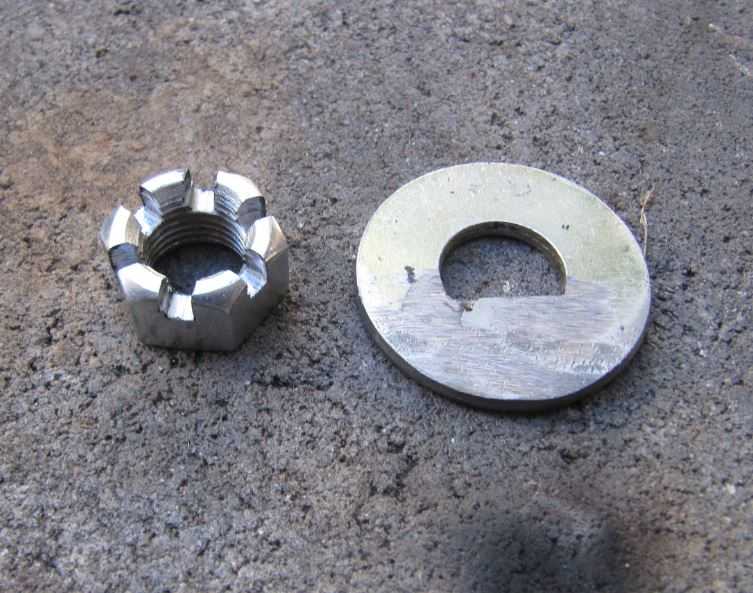
This nut was the same thickness as the correct one but was 1/16 inch smaller across the flats. That concerned me a little, so I bought new nuts and D washers from Victoria British. The D washers were fine, but the castle nuts were identical to the one I made. I couldn't find the right nuts anywhere. Sigh. I eventually found the missing D washer, but not the nut. I guess these "undersized" nuts are OK, but I'd rather have the original ones.
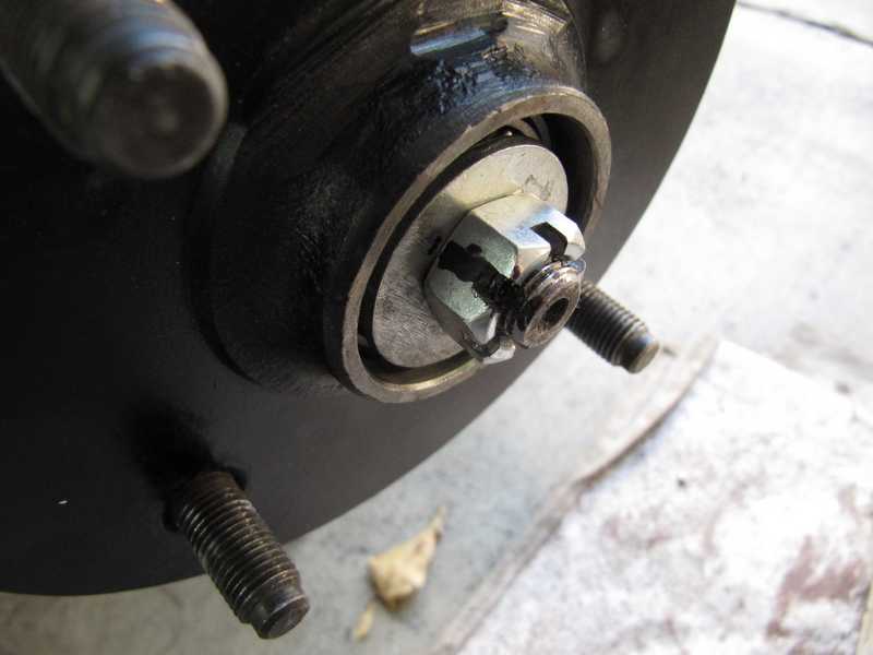
The hub adjustment is well described in the shop manual. First the hub is installed with the bearings in place but without grease or the inner seal. It is finger-tightened, and the nut is backed off until a slot lines up with a hole in the spindle. The end float is then checked; it should be less than 5 mils. The position of the nut is then marked, the hub is removed, the bearings greased, and the felt seal installed (wet with oil). The brake disk, which must be installed before the hub, can then be installed and the hub slid onto the spindle. Finally, the nut is reinstalled, set to the previously marked position, and the split pin, which holds it all together, is inserted.
Steering Rack
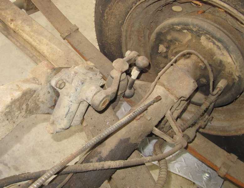
The rack, while superficially ugly, was actually in decent condition, but it still needed cleaning, painting, and regreasing The inner tie-rod joints felt good, and the adjustments at the steering pinion, made with shims, were at least close to being correct. I went through the adjustments anyway, to be sure they were right. The boots were goners, though, and the tie-rod ends, while tight, felt unlubricated.
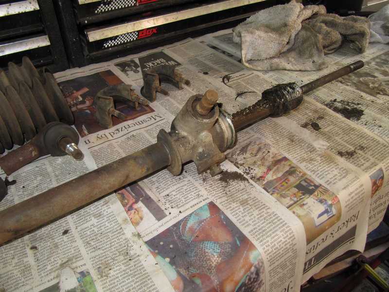
The old grease in the rack was like hardened chewing gum. It takes a decade, or probably more, for grease to harden that way. Fortunately, it came off easily with solvent and a little scraping. Big mess, though.
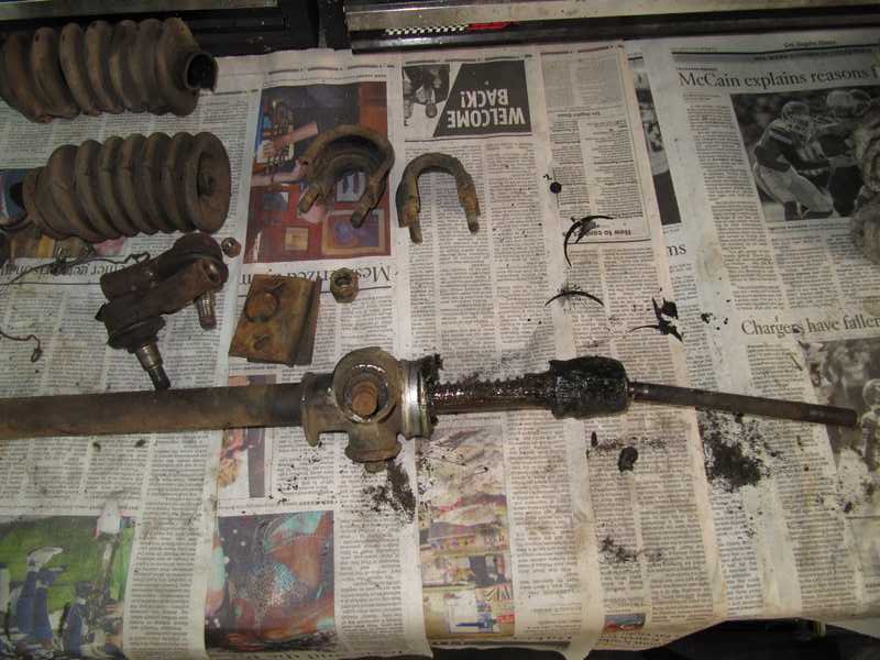
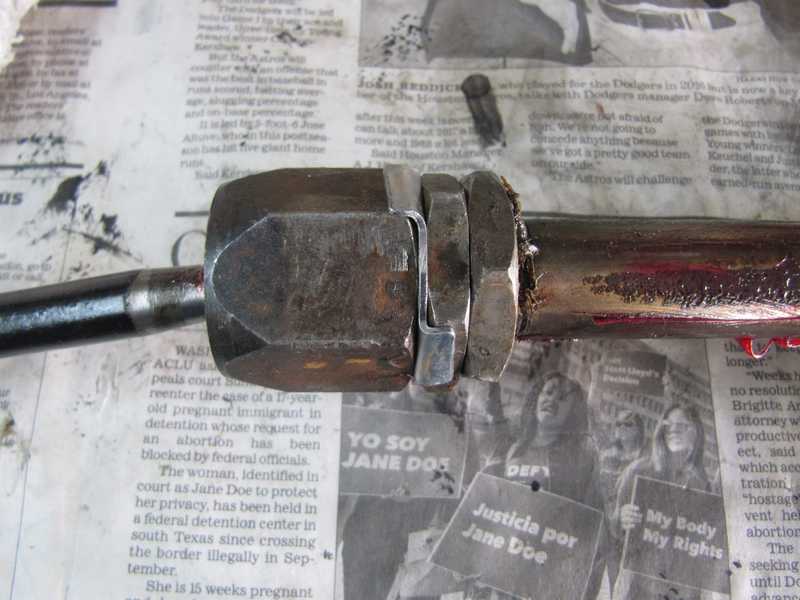
Removing the inner joints of the tie rods wasn't easy; they were really tight. The joints have three parts: a cup nut (the outer one), a sleeve nut, and a lock nut. The cup nut has a tabbed lock ring, which is often hidden under old grease.
Disassembling the joints is a dilemma, as there are three nuts tightened against each other, and it's not realistically possible to hold two while turning the third. To disassemble each joint, I first bent back the lock-ring tabs, put the cup nut in a vise, and used an 18-inch crescent wrench on the locknut. That removed the cup nut. I then put the sleeve nut in the vise, loosened the lock nut, and the rest could then be disassembled. If the lock nut had come loose first, the cup and sleeve nut could have been removed together. Separating the two would then have been relatively easy: hold the cup nut in the vise and use a socket or large wrench on the sleeve nut.
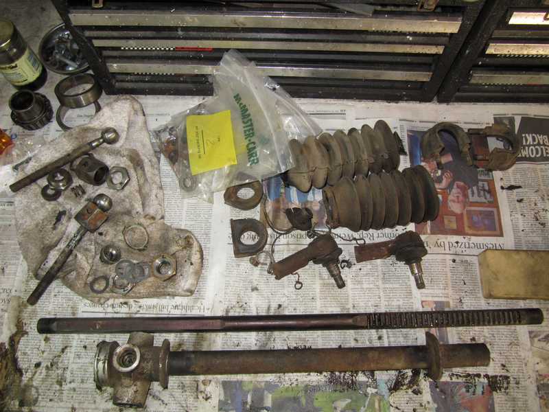
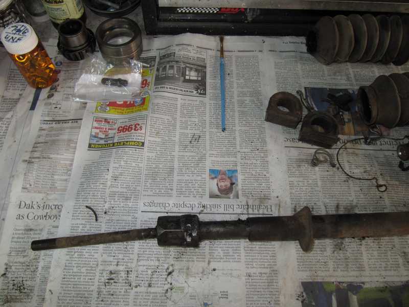
The tie rods looked good. I galvanized their threads and painted their shanks. Cleaning the rack required a full day of soaking in solvent; I painted the steel part but left the aluminum body natural, as it should be.
The shop-manual instructions for setting up the rack are pretty good; mainly, it involves measuring and messing with shims to remove end float. The first step is to determine the number of shims for the pinion gear; the idea here is to reduce the end float as close to zero as possible without preloading the pinion.
Under the cap is the "thrust button," which, along with a spring, puts some loading on the rack. Shims here are selected to allow a little end float (4 mils) in the absence of the loading spring. I galvanized the cap and replaced its plug with a grease fitting; I also greased all the parts as I assembled them.
The next step is--you guessed it--select the shims for the inner tie-rod ball joints. The idea here is to take out all the looseness in the joint. The manual gives a maximum looseness of 0.002 inches, but that is impossible to measure. Best thing is to add shims until the joint is just short of binding, and there is no perceptible looseness. Also--how many times have you seen the tabs on the locking washer all bent in the same direction? Think about it--that won't lock anything! Two must be bent in one direction and the third in the opposite direction. (Actually, bending it correctly probably won't, either. See my rant, above, on locking plates. The locking plate is necessary for spacing, though, so it has to be in place.)
With the addition of tie-rod ends and boots, the rack was finished.
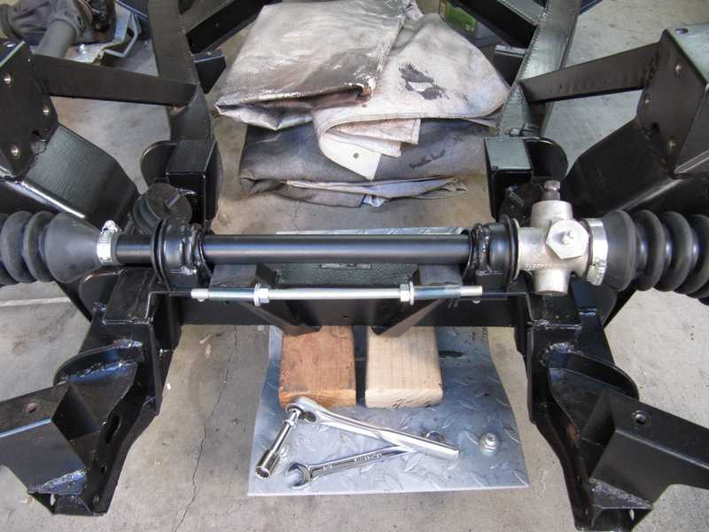
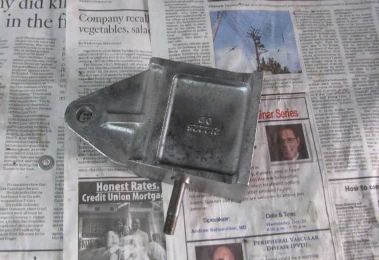
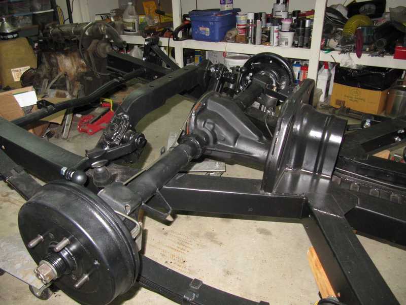
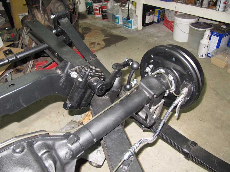
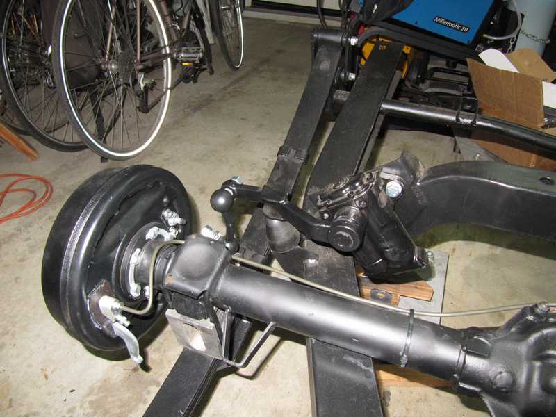
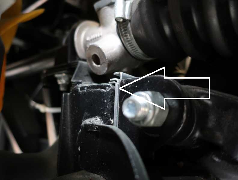
The manual describes a complicated method for setting up the mounts. The underlying idea is that the mounts should be pushed outward as far as possible, and the flanged plates underneath the mounting brackets should be at their maximum inward position, with the flange toward the inside of the car. That keeps the rack assembly tight, so it won't shift side-to-side in use.
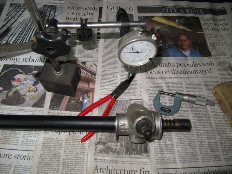
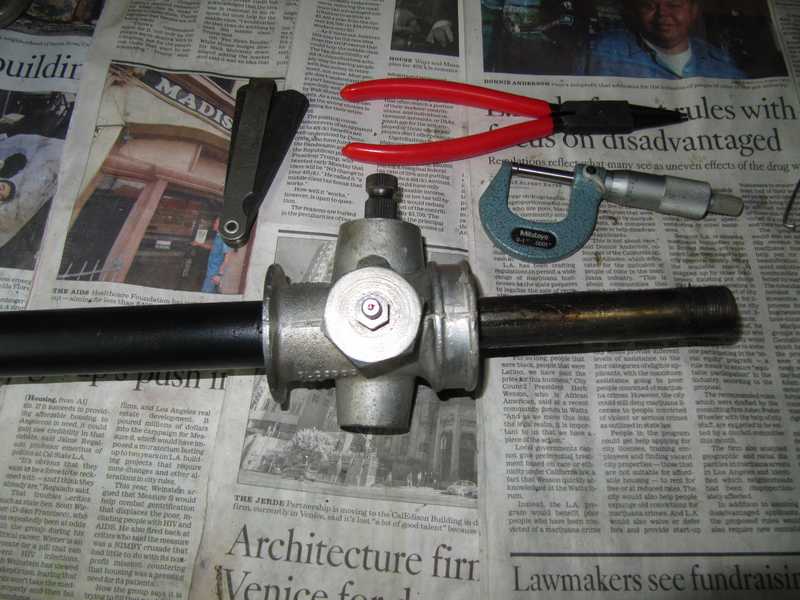
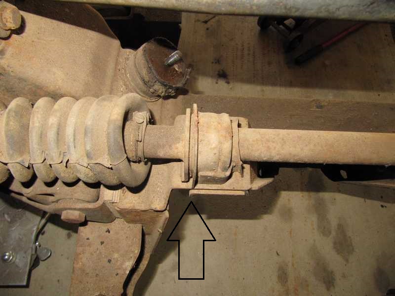
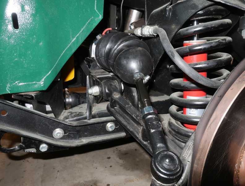
It's worth mentioning that the rack is almost always installed wrong. Indeed, it was installed wrong in the car as I received it. Take a look at the picture below. The lip on the plate below the mount (arrowed) should be toward the center of the car, so it prevents the mount from sliding and loosening. Both were backwards. With that orientation, they functioned simply as washers and didn't really do the job they were designed for.
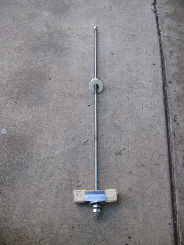
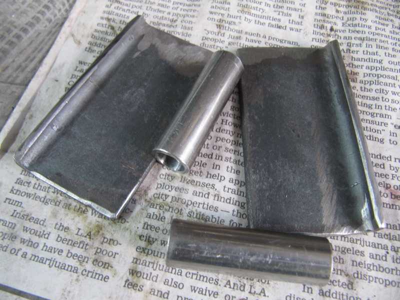
The manual specifies a special spreading tool, which is not available any more, so I made my own, shown below. It consisted of flat pieces, which apply force to the rack mounts, and a threaded rod with nuts to provide that force. Because the rod was off to the side, the flat "pushing" pieces would tend to turn inward; that's not desirable, as we want their edges to remain perpendicular to the rack's axis. To ensure all this, the tubes in the pushing pieces, into which the rod fits, had to be collinear, square to the pushing surfaces, and a close sliding fit over the threaded rod.
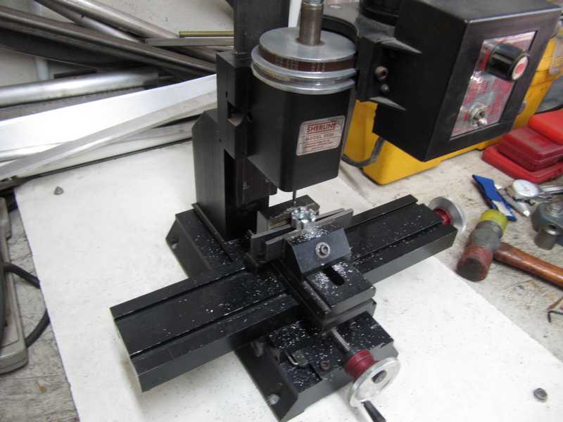
The tool was made from cut-down angle iron, 3/8-inch ID steel tubing, and 3/8-inch UNF threaded rod. I trimmed the tubes in my lathe and the flat parts in my milling machine. Initially, the seam on the inside blocked the threaded rod when I tried to insert it, so, to clear it, I ran a 3/8-inch drill through the tubes.
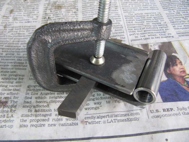
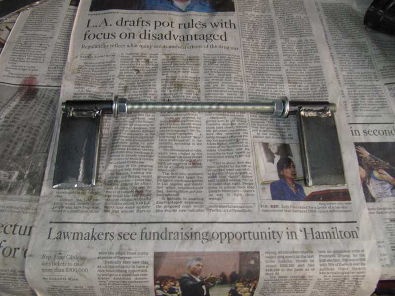
The setup for welding the tubes is shown in the second picture below. The rectangular thing between the plates is a 1/4-inch lathe tool blank, used as a spacer. It places the center of the tube, which is 1/2-inch OD, level with the upper side of the flat piece. I held it together manually while tacking it, then finished the weld normally. The completed tool is shown in the last picture.
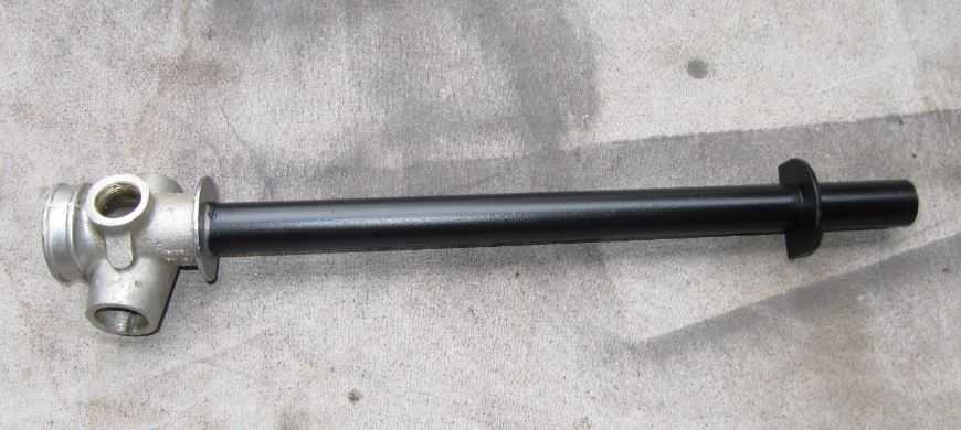
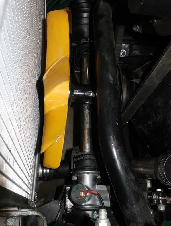
The pictures below show the tool in use and the completed, installed rack.
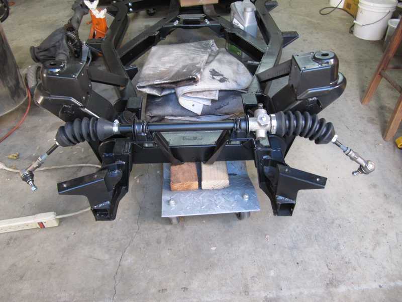
Although I installed the steering rack before the suspension, I later discovered that installing some of the suspension parts would have been easier without the rack in the way. If I ever do this again, the rack will wait until the front suspension is in place.
Second Try
When I got the car on the road, I discovered that the steering had quite a bit of play in the straight-ahead direction. All cars of that era had at least a little, but this car had about four inches, which was quite a bit too much. It was difficult to keep the car on a straight path.
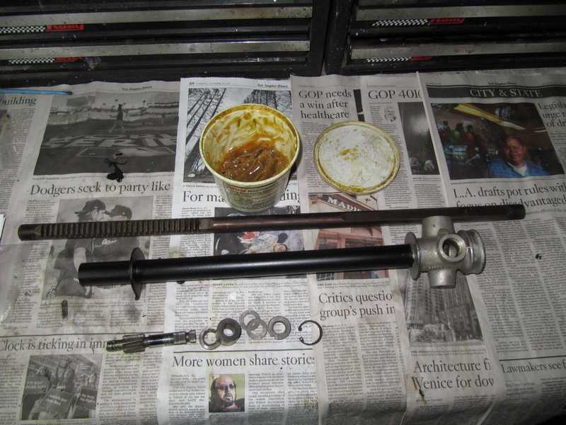
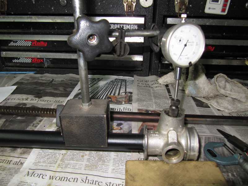
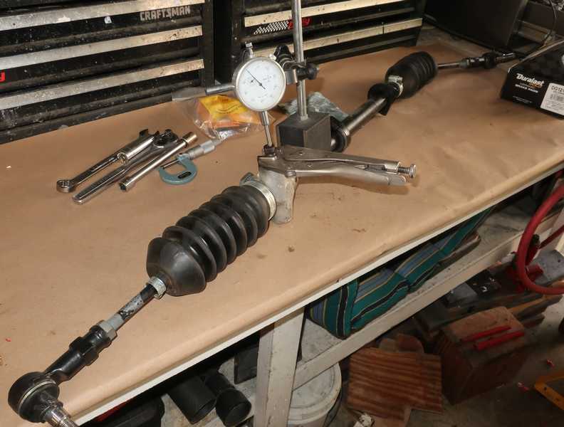
Realizing that I couldn't check the pinion set-up with the rack in the car, I removed it and checked it on my workbench. I measured end float of 10 mils at straight ahead (it should be close to zero) and 2 to 10 mils in other positions. Something clearly was wrong, so, to figure out what was going on, I disassembled the rack. I found that the pinion gear had extensive rust pitting; it's easy to see how that could lead to excessive play.
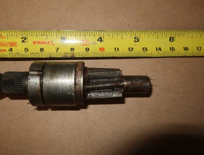
I'm surprised that I didn't notice all this when I was restoring it. The pitting was probably caused by long use combined with inadequate lubrication and, perhaps, water infiltration.
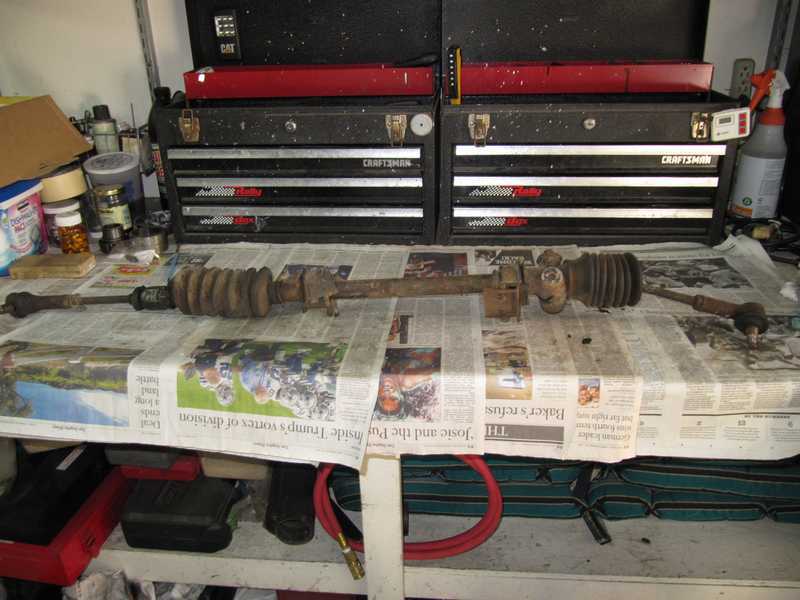
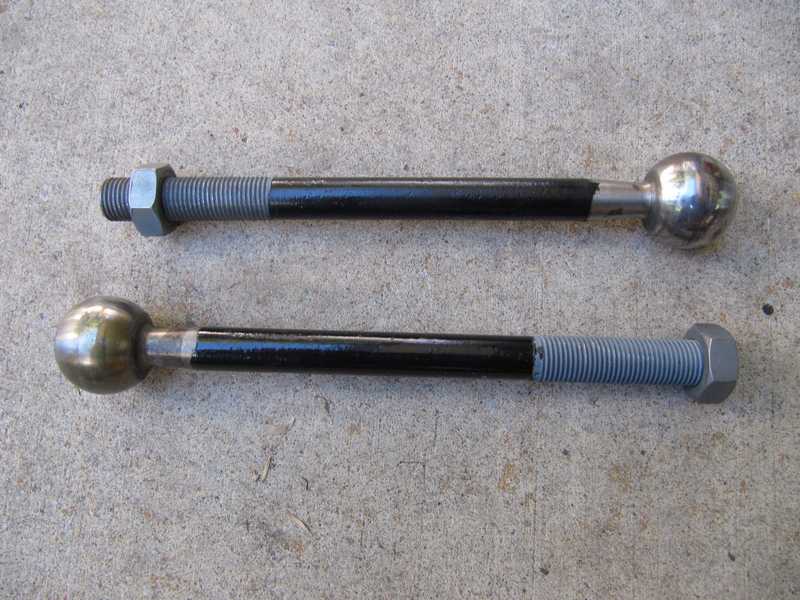
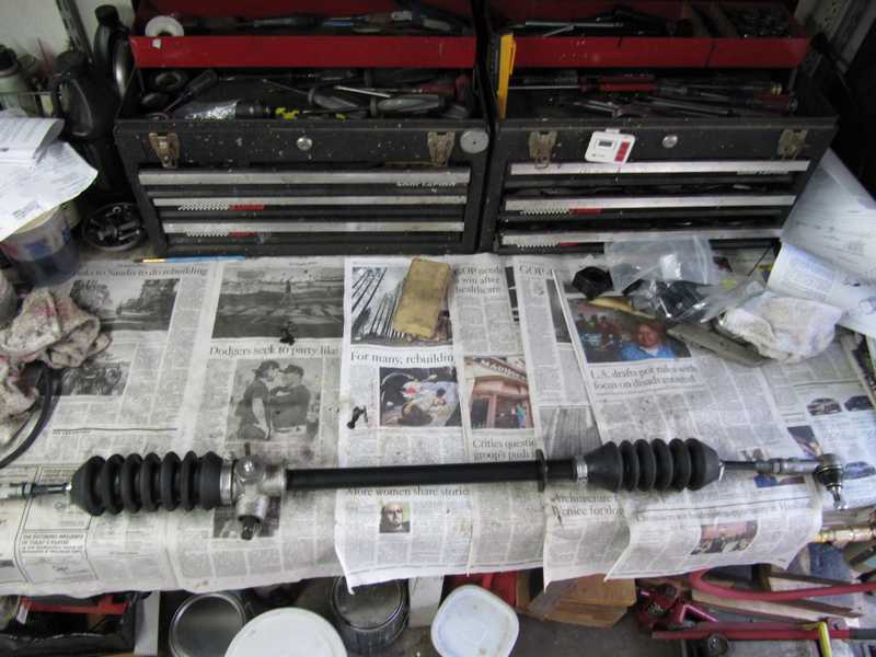
I didn't want to mess with this any longer, so I bought a new rack and installed it. Below, the new and old racks are compared. I transferred the tie-rod ends to the new rack and set their spacing as close to that of the old rack as possible.
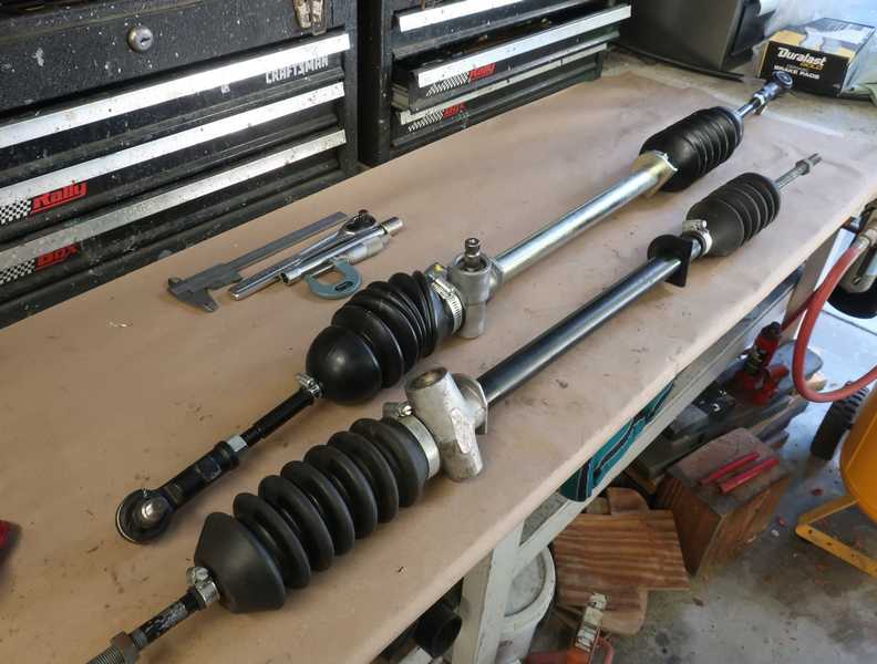
Installing the new rack was straightforward, but the area is a little tight.
Unfortunately, with the new rack, I had to realign the wheels, but only the toe-in needed to be set; changing the rack does not affect the camber, and the TR4A's caster is not adjustable. I was also able to center the steering better; my previous efforts were not quite perfect. The car now has zero steering play and tracks nicely.
I planned to replace the failed pinion with a new one from Rimmer in the UK, thinking that it would make the old rack useful as a spare.
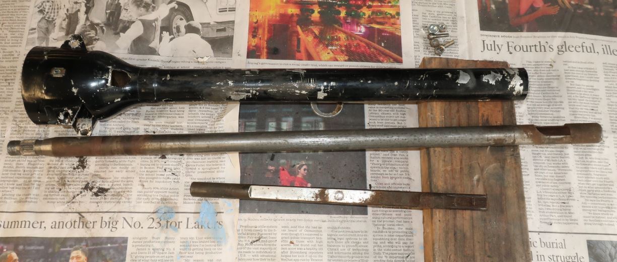
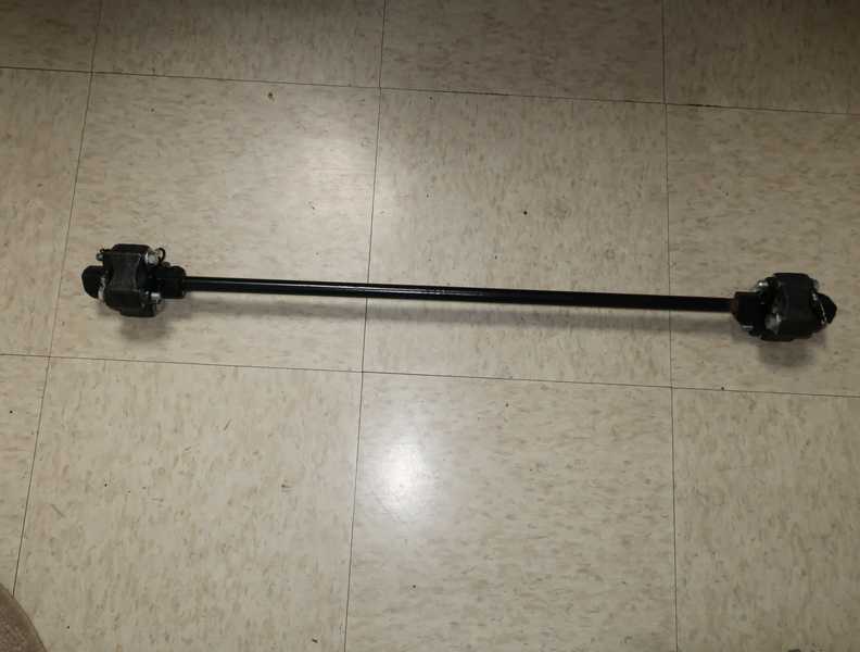
Steering Column
The outer part of the steering column was pretty beat up, but the shaft was fine: perfectly straight, with just a little light rust. The rubber in the joints had hardened, so I bought new ones. I also bought new bushings for the column; the existing ones weren't bad, but they probably wouldn't have lasted for the car's next fifty years.
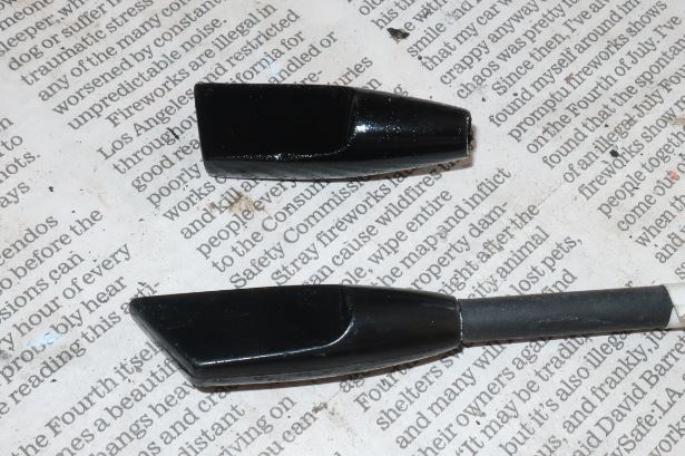
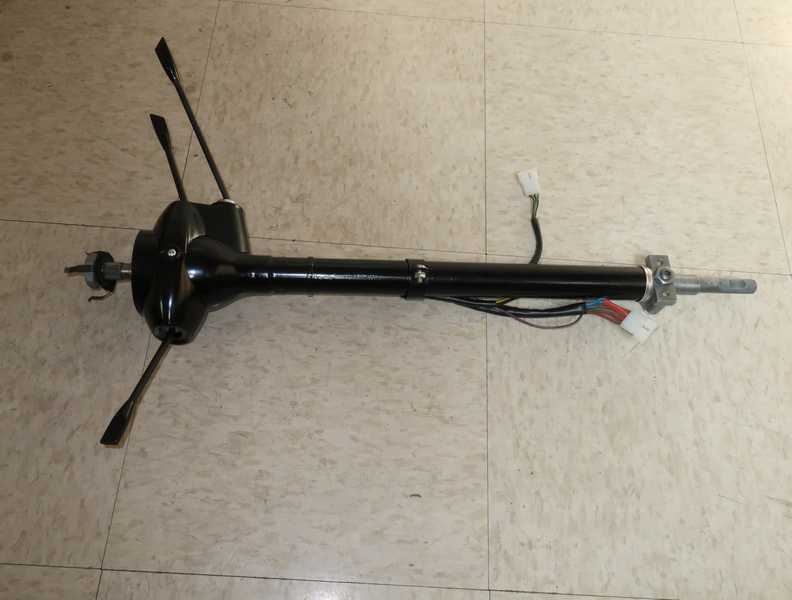
The column switches were in good condition; clearly, they were not original ones. The light switch (the most expensive and hardest to obtain, naturally) had a broken paddle. I made a new one on my lathe. The new one (top) and an original are shown below; it's not perfect, but it should do.
The restored steering column.
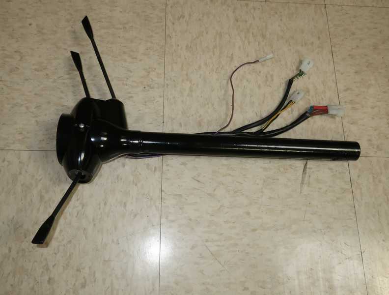
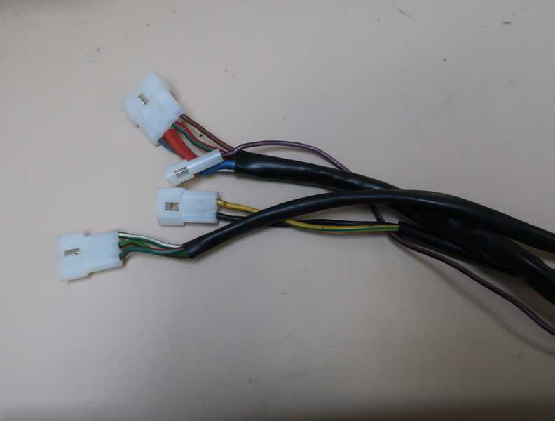
The electrical connectors for the steering-column switches, like all wiring-harness connectors, are Molex. They should be much more reliable than the original, hopeless, bullet connectors.
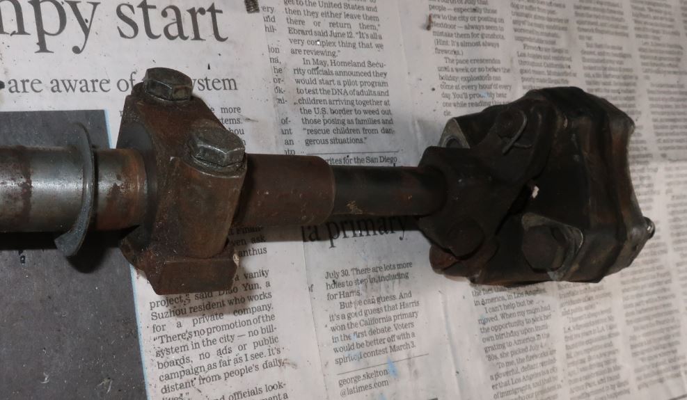
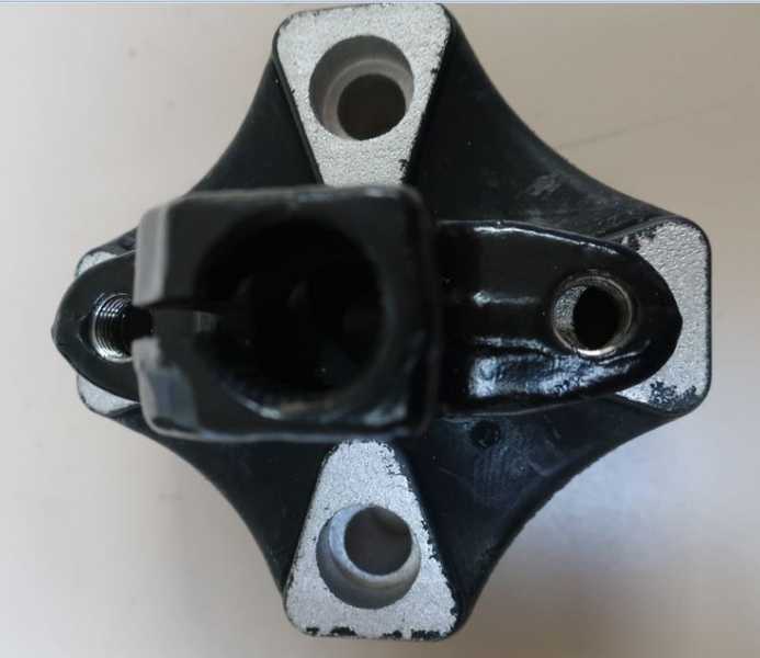
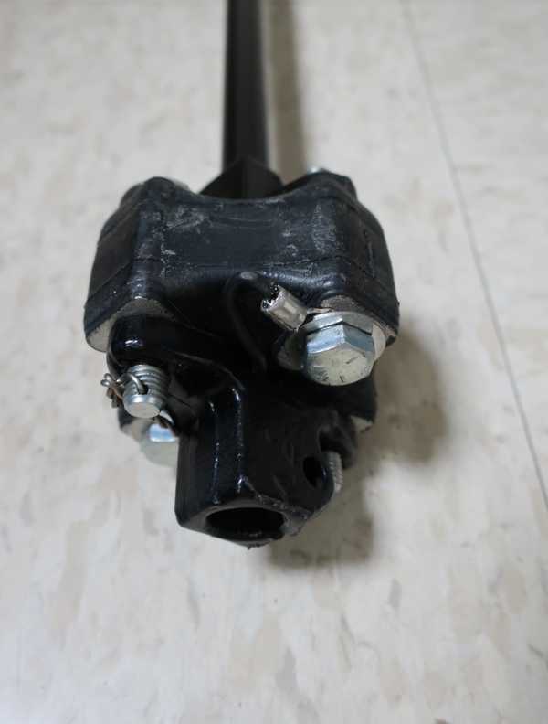
The steering shaft has two rubber universal-joint couplings. True to my experience, the modern replacement parts I bought were not made right. The holes did not match the fittings on the steering shaft; they were 1/8 inch too far apart. In the picture below, the holes on the left are lined up, but the ones on the right are clearly off. (Looking into the threaded hole, you can see part of the coupling at the bottom, on the left, showing that the holes are not aligned.) To align them, I put the coupling in a vise and squashed the little bastard a bit; it is rubber, after all. I then could insert and tighten the bolts. I couldn't think of any reason why that might have been inadvisable, but time may inform me better. Meanwhile, I'll save the old parts.
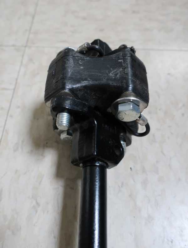
With a little help from my large vise, it all went together as it should.
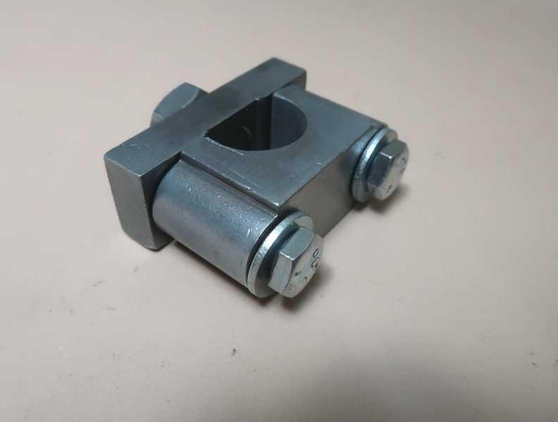
I galvanized the steering-column clamp. I don't think it had been plated previously. I also galvanized the end of the shaft; I didn't see any point in trying to plate the entire shaft.
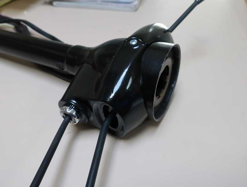
Below, the completed upper steering column.
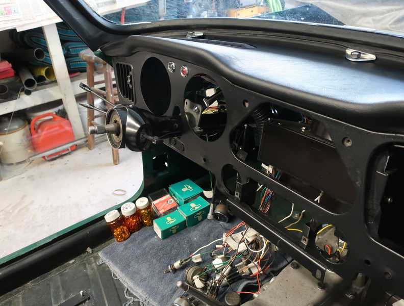
Finally, here it is, installed.
Rear Springs
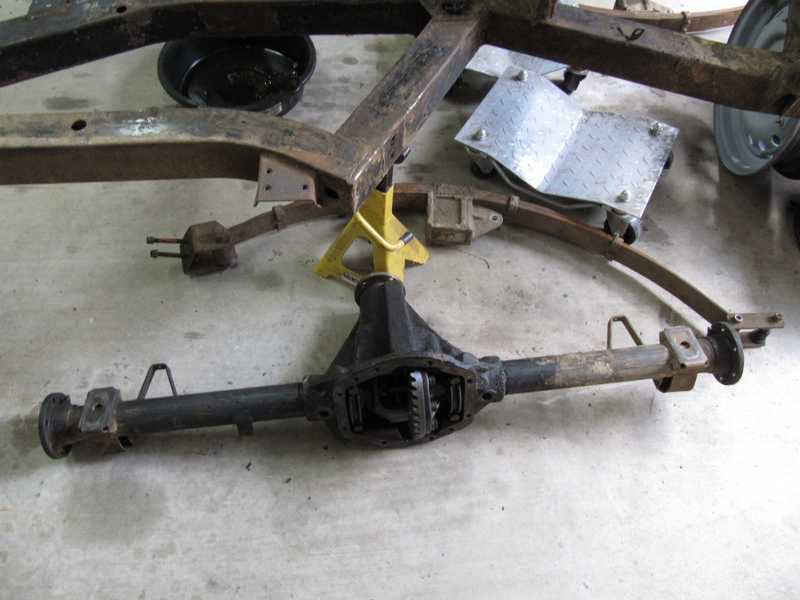
The rear axle is attached to the spring by a pair of long U bolts. A large aluminum spacer sits between the axle and the spring, as the axle is located above the frame. A bit unusual, but there it is.
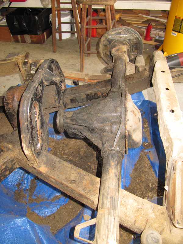
Removal of the axle was easy, since almost everything attached to it had been removed. I just unbolted the U bolts and lifted it off. Before removing it, though, I drained it well and scraped off as much crud as possible. I also removed the rear brakes, hubs, and axles.
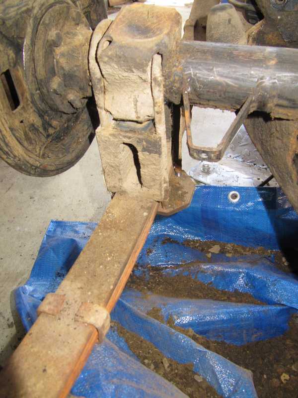
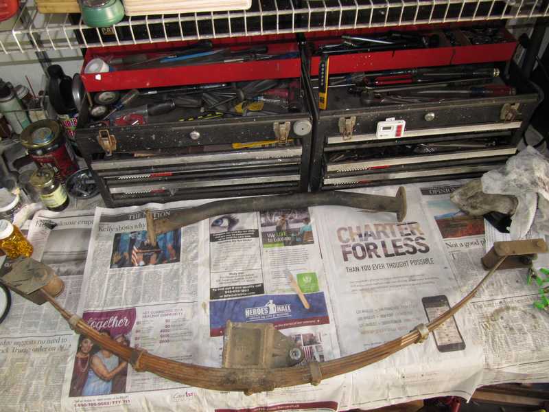
I didn't disassemble the springs until I was ready to work on them. Removing the shackles from the frame showed how badly the spring bushings had deteriorated.
The springs and all their parts were rusty and dirty, but they were OK under the schmutz.
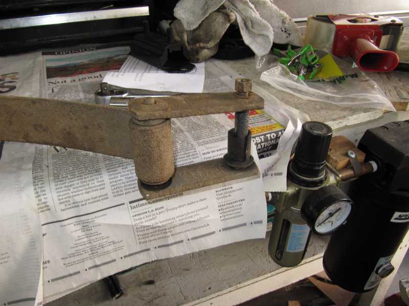
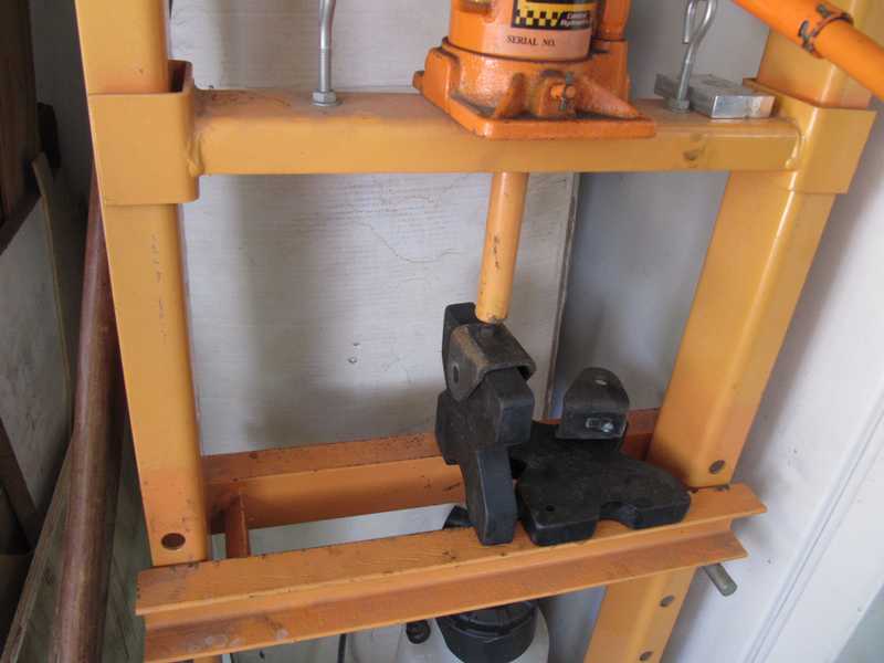
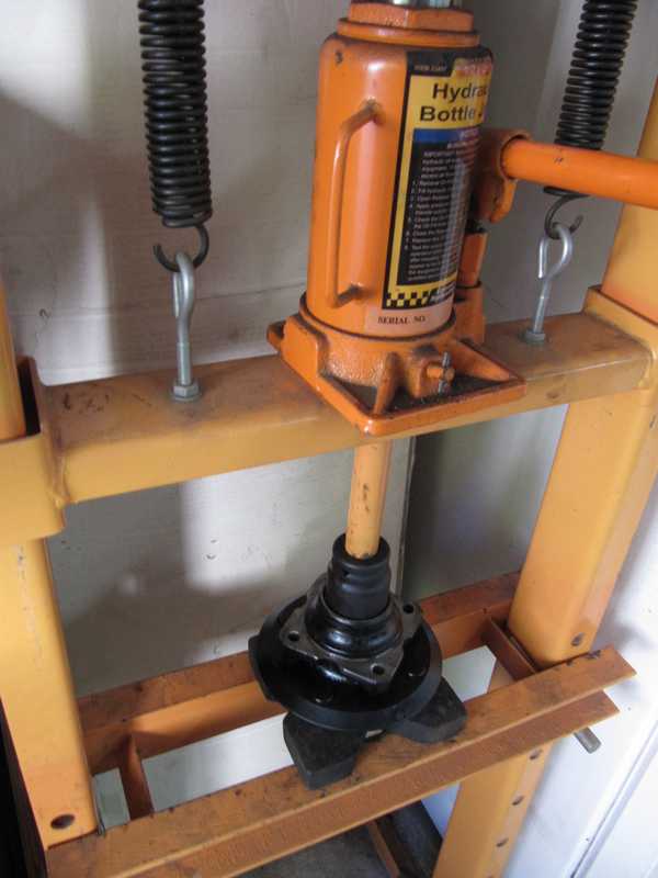
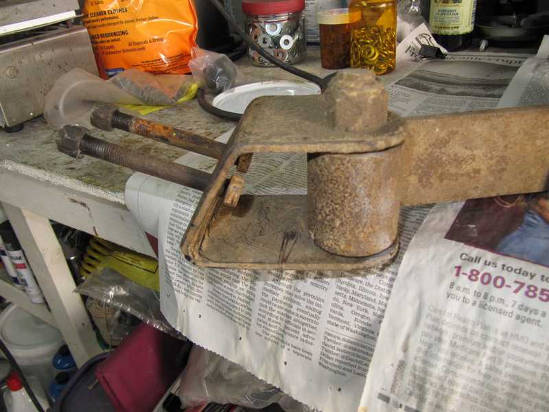
Removing the front bushing was not easy. It had to be pressed out with a hydraulic press. Supporting the spring for that operation was tricky, as the spring is heavy and awkward.
I washed all the spring pieces in detergent, wire-brushed off the worst of the rust, and gave the spring a coat of rust-converting primer. In the picture below, it sits with a pile of other primed parts, waiting to be painted.
It's not realistically possible to disassemble the springs, as I did with my MG TD. I would have liked to, as I'm sure there is rust between the leaves and it would be good to remove it and paint the surfaces. There are limits, unfortunately, to what we can do.
The cast aluminum spacers cleaned up nicely.
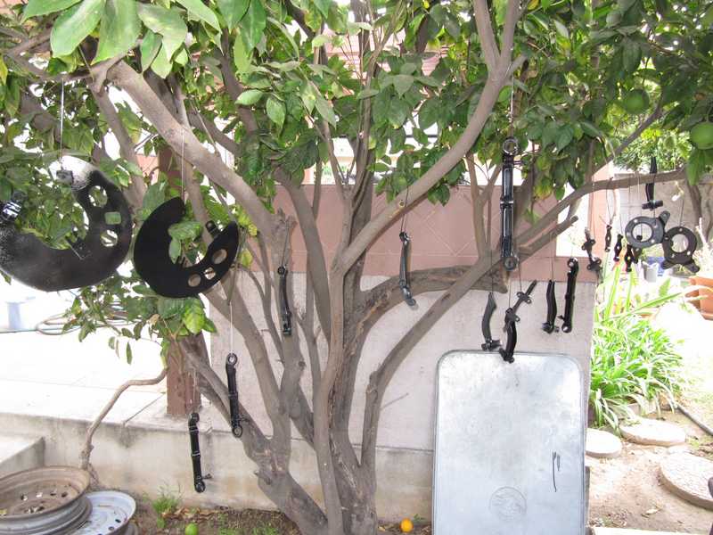
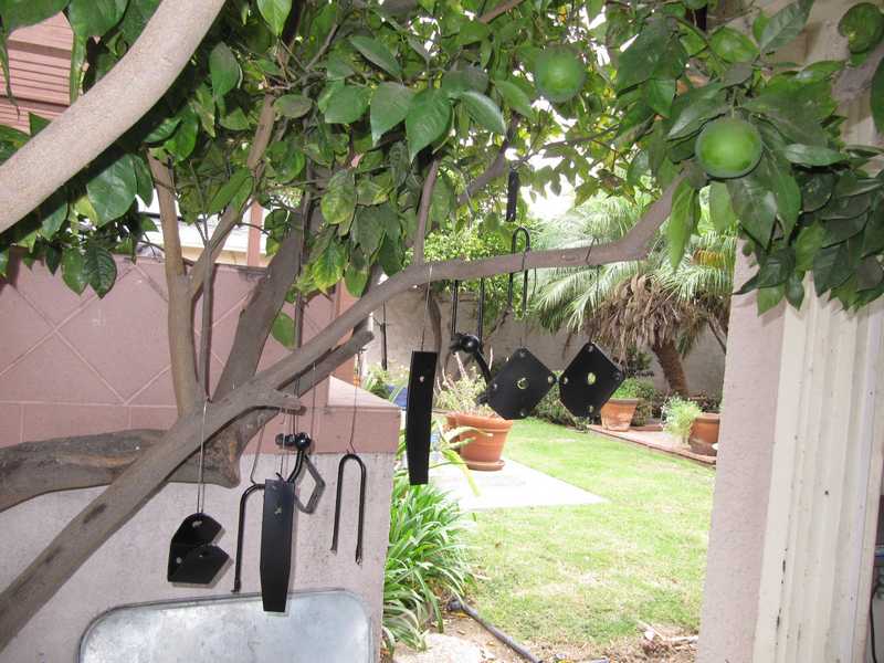
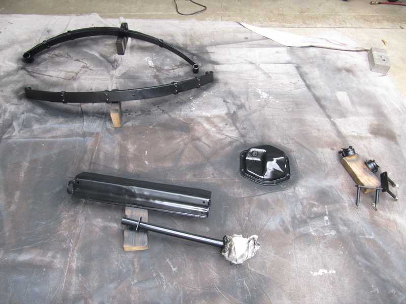
Since I use a paint sprayer, which requires some effort to set up and clean, I try to paint parts in large batches. Below, a set of parts, mostly rear suspension, are set out on a heavy canvas dropcloth for painting. Once they were painted, I hung the smaller parts from the orange tree to dry and left the larger ones on the drop cloth. I gave all the parts at least two coats of paint, the same Rustoleum semigloss I used for the frame.
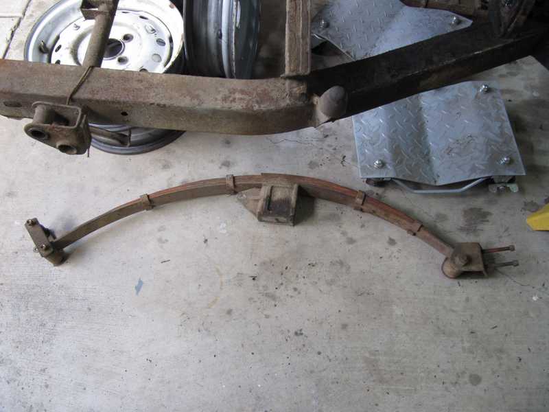
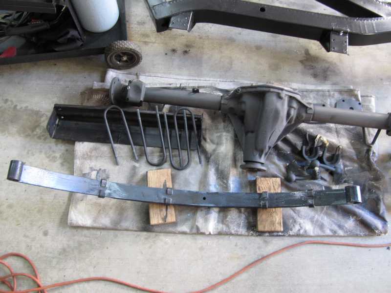
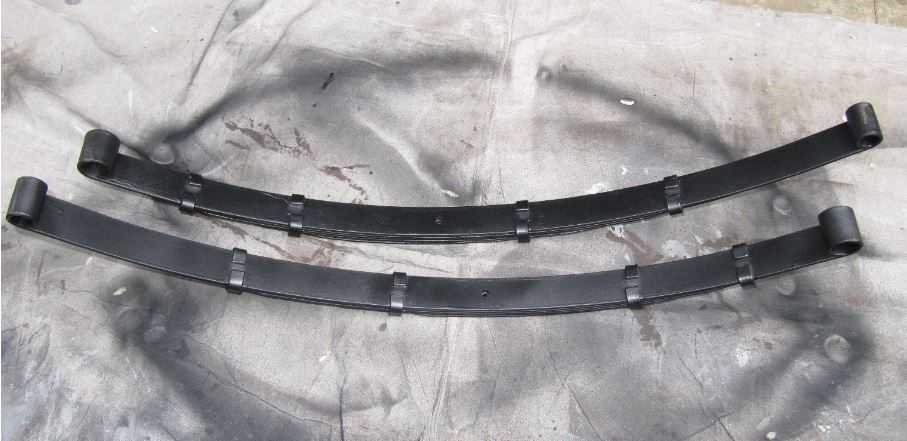
The restored and painted springs are shown below.
Rear Suspension
I bought rebuilt shocks from World Wide Auto Parts. There is a lot of information on the web about rebuilding lever shocks, but it was something I just didn't want to mess with, and Peter at WWAP did a superb job for me previously, on my MG TD shocks. I installed the shocks as soon as they arrived; they were the first parts installed on the completed frame.
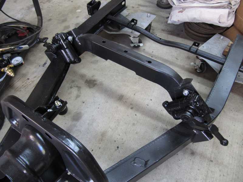
The rear springs were mounted on the frame with new hardware and bushings. The bushings' fasteners were not tightened at that time; they shouldn't be tightened until the car's full weight is on them.
The rest of the rear suspension comprises parts of other systems in the car: the rear axle, brakes, and the differential. Those are described on other pages. The restoration and installation of the rear axle is on the Drive Train page, the front and rear brakes are on the Brakes page, and the differential has its own page. A description of the restoration of the rear hubs somehow wound up near the end of the Drive Train page.
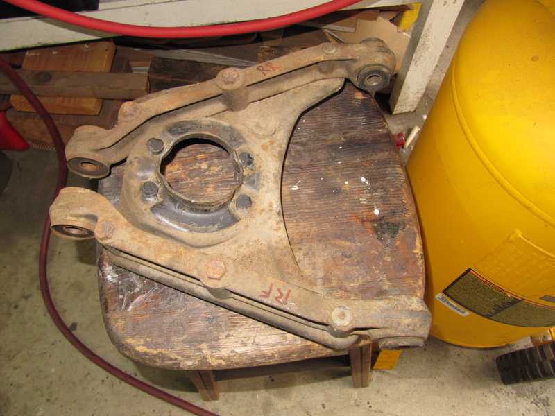
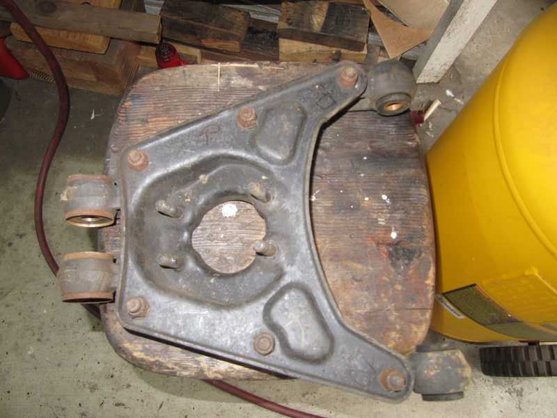
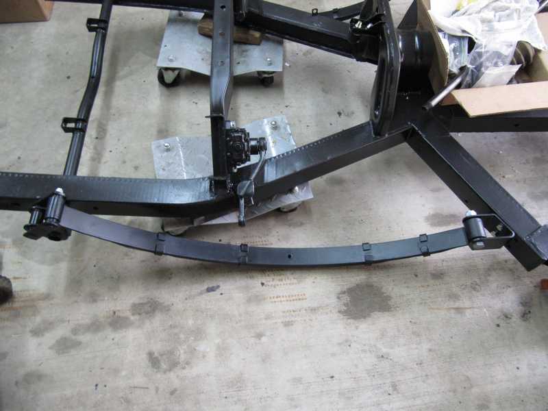
The rear axle is mounted on top of two large, aluminum blocks. Each is attached with a single nyloc nut, which also holds the lowermost spring leaf in place. Plates with beveled corners provide the attachment points for the U-bolts that hold the axle in place. The plates are installed with the beveled corners pointed toward the front; their orientation confused me a little, as I had noticed, on disassembly, that the corners were pointed toward the inside. That's evidence that the rear axle was removed at some point.
Below are some pictures of the rear axle and suspension. It's finished, barring a few details. Tightening the spring bushings and connecting the shock links had to wait until there was more weight on the suspension.
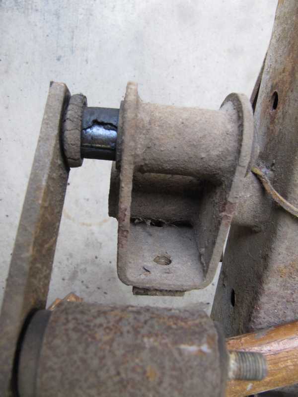
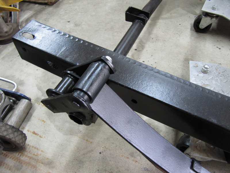
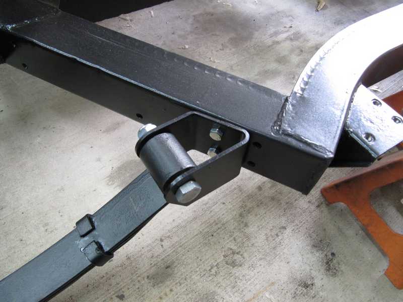
Somewhat later, I realized that the shock links, as shown in the pictures above, were not installed correctly. I had copied the orientation in the car as I received it, shown in the first picture, below, which was not right. The correct orientation is shown in the TR4A parts-list diagram.
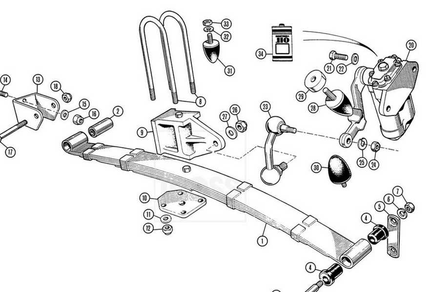
The plate on the underside of the spring, to which the U-bolts attach, initially was also oriented wrong (you can see that here), and, as I restored the car, I documented a few other things that similarly had been incorrectly assembled. I'd like to say that it's best to check original sources, not just copy what's there, but the original sources also have errors. I found two major ones in the shop manual, and the incorrect differential seal sold regularly by the usual suppliers is traceable to a parts-list error. God knows what other errors are lurking in those documents.
Pictures of this part of a solid-axle TR4A are not abundant on the internet, but I found one good picture confirming that the shock-link orientation shown in the parts list is correct. I later removed the links and corrected their installation.
Tires and Wheels
Original Tires and Wheels
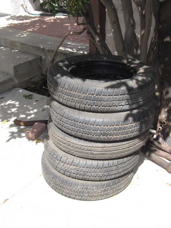
The tires that came with the car were at least 20 years old, so they clearly had to be replaced. I wasn't sure whether I wanted to use its wheels or get new ones. It depended in part on their condition, as they're not worth the cost of straightening. I took the tires off the wheels fairly early in the project, while I still had a hub available for checking the wheels' straightness.
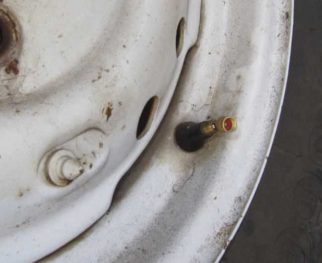
The first steps were to remove the valves and balancing weights. The valves are removed by a special tool, which simply unscrews them. There is also a special tool for removing the weights, but I don't have it, so I pried them off with a screwdriver. This risks marring the finish, but, if I decided to use these wheels, they would be repainted anyway.
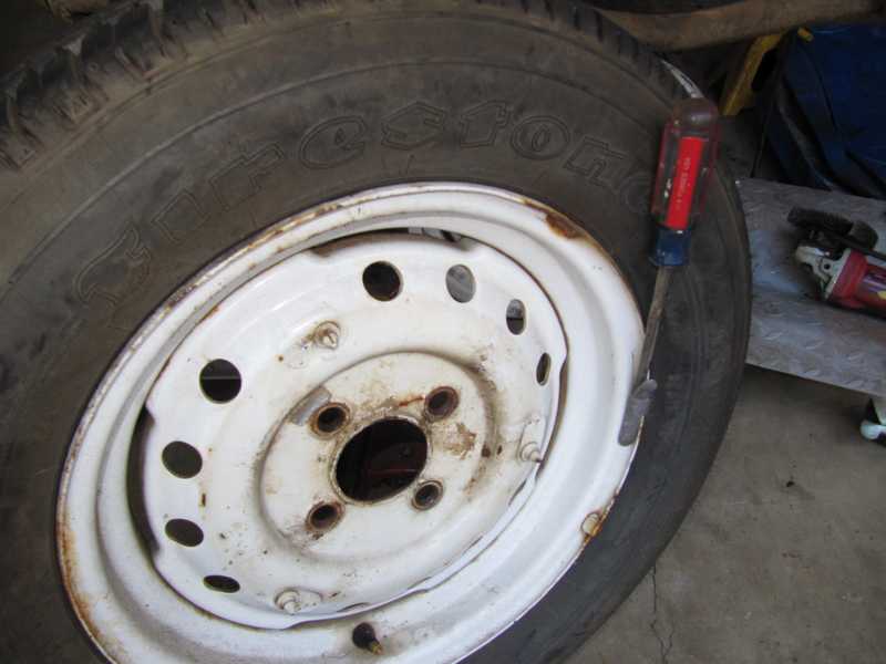
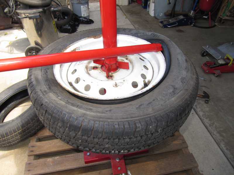
Before removing the tire, it's necessary to "break" the bead; i.e., move it off the rim, toward the inside. The tire tool has a bead breaker, but it doesn't work very well. It was easier to break the bead by laying the tire on the ground and standing on its sidewall. Occasionally a bead was a little tight, but by moving my weight around a bit and adding some soapy water, it eventually came loose. Both sides had to be loosened.
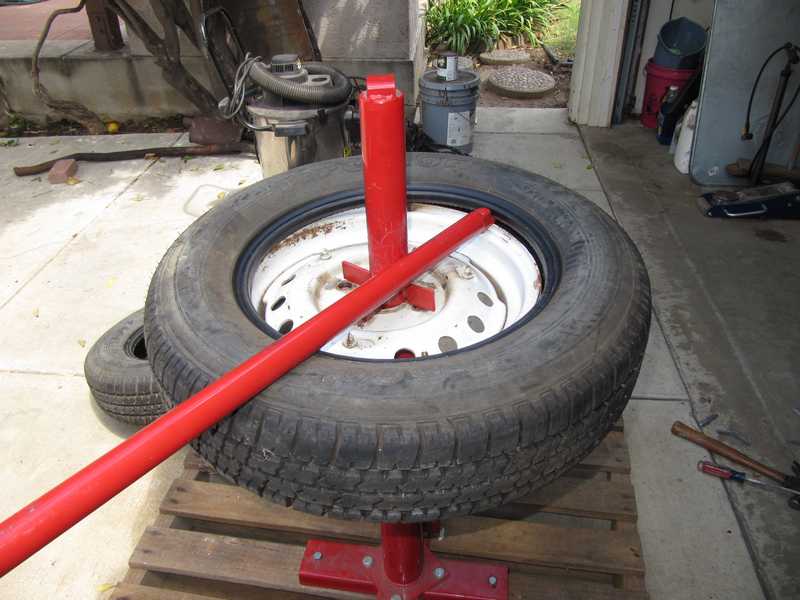
The tire tool is straightforward to use. Just put the end of the tire iron under the bead and pull it around in a circle. A little soapy water helps here, too.
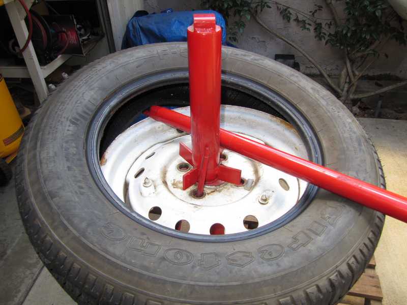
The lower bead was removed similarly. It always seemed fairly easy to remove, once the upper one was done.
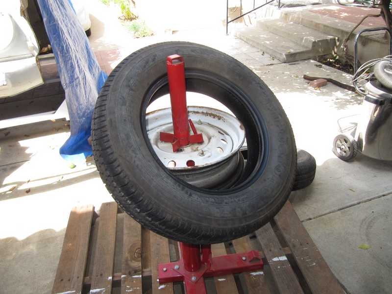
Finally, a pile of old tires and one of wheels.
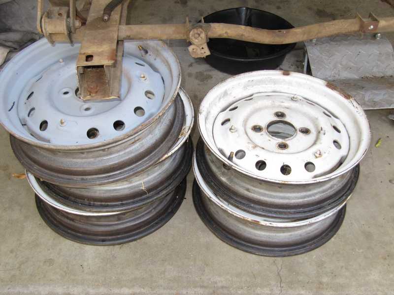
To check a wheel for straightness, I mounted it on a front hub, spun it, and measured the lateral and radial run-out of both inner and outer rims with a dial micrometer. The first one I checked was so bad that I didn't bother to measure the rest. I realized that my future held some new wheels.
New Tires and Wheels
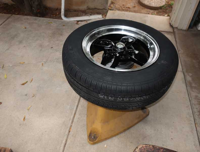
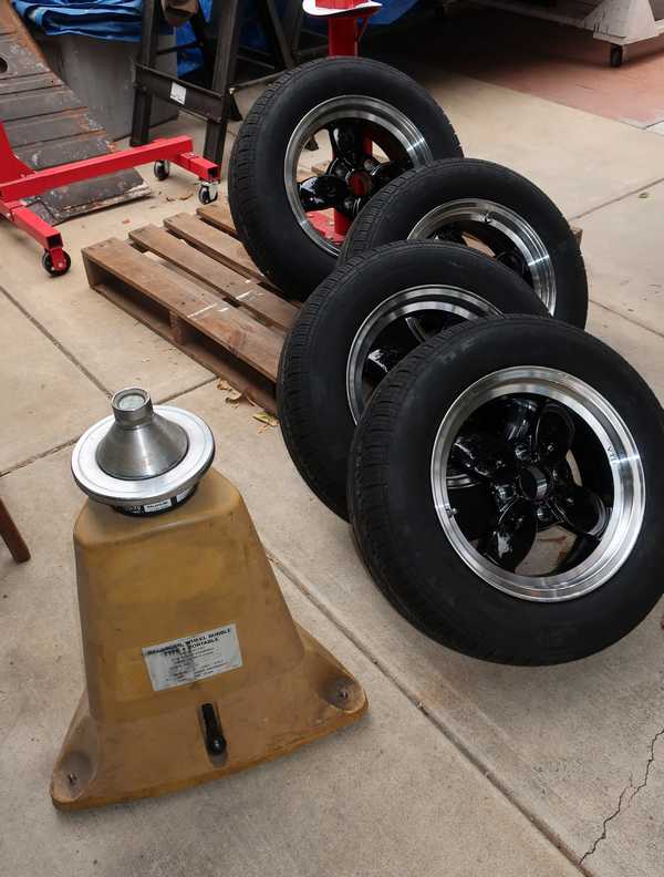
I bought a set of 15x6 VTO wheels and a set of Federal SS657 tires in 195/65R15 size. This tire size is a common choice for TRs that have 6" wide wheels. (The original wheels were 15x4; this tire would be too wide for those.) I mounted them myself, with considerable care to avoid scratches, and balanced them with my venerable Coats bubble balancer. I have done this in the past with my Porsche and my MG TD. Although modern, dynamic balancing is technically superior, wheels balanced this way have no discernible vibration to at least 75 MPH. And this is, after all, the way that all tires were balanced back in the 1960s, when the car was new.
I should note that modern balancers can detect lateral as well as radial imbalance; my balancer detects only radial. This is OK for the relatively narrow tires used on older cars, but for the much wider tires used on modern cars, it's probably not adequate. On those, the possibility of lateral imbalance should be taken seriously.
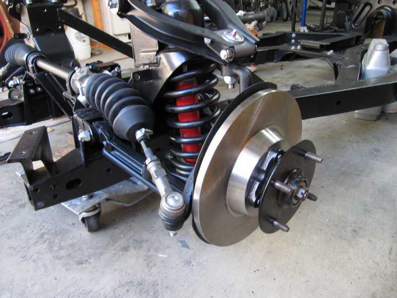
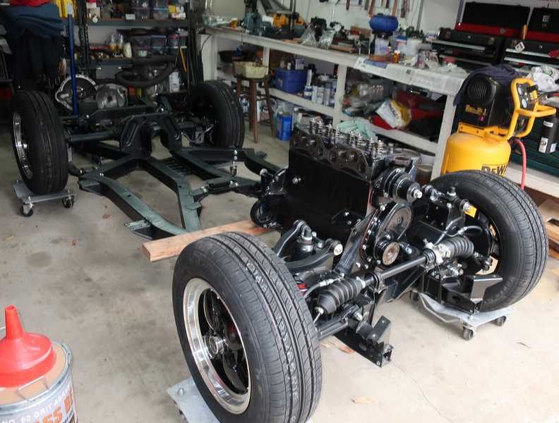
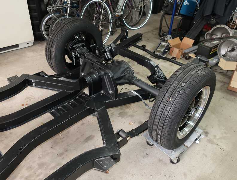
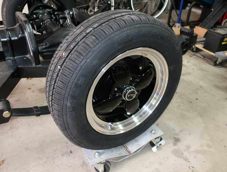
Mounted on the chassis, the wheels and tires looked really slick.
Spare Tire
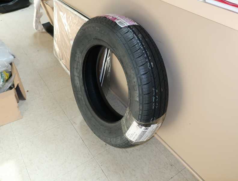
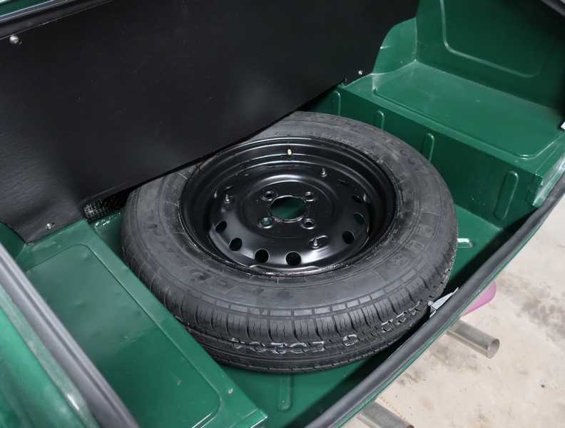
At first, I planned to do without a spare tire, as I probably would never need it. However, my Law of the Innate Perversity of Life states that if I didn't carry one, I'd have a flat for sure, but if I had one, I'd never use it. So, to protect my new tires and wheels, I bought a spare. I got the same tire in a narrower width, so it would fit an original, 15x4 wheel. (Also, the wider tires, on the VTO wheels, would not fit into the trunk's spare-tire well.) Of course, it's generally a bad practice to drive on mismatched tires, but it should be OK in unusual circumstances, in a "limp home" mode. Kinda like those mini-spares you find in cars today.
I measured a few of the original wheels and selected one that was within straightness specs. I sanded, primed, and painted it with the same semigloss black I used elsewhere in the car.
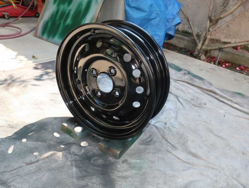
I'm not sure what the original color was; probably a cream white, as that's what I see most often on the few remaining cars that still use steel disk wheels. For this one wheel, which will be hidden in the trunk, I saw no need for originality.
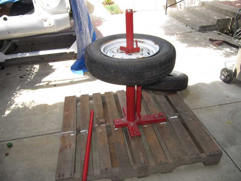
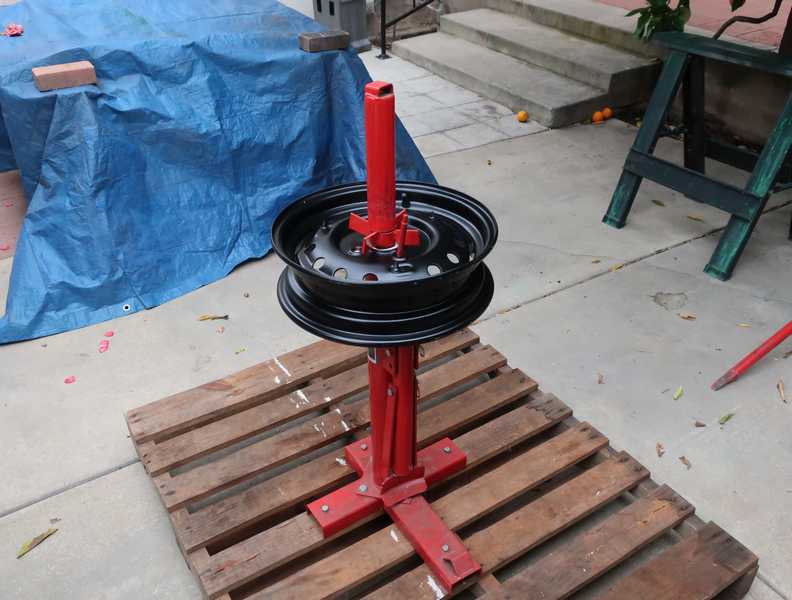
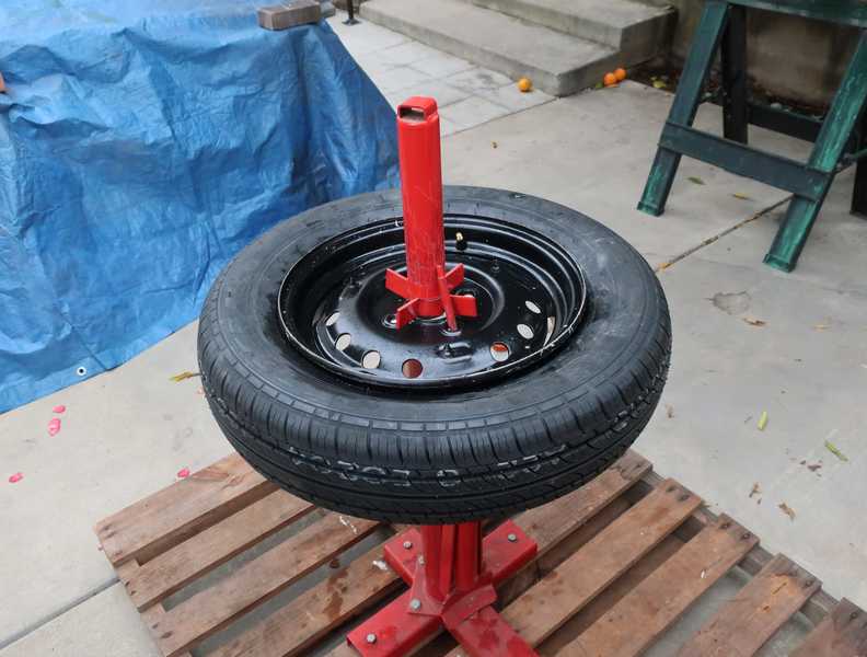
The tire was mounted in the usual way.
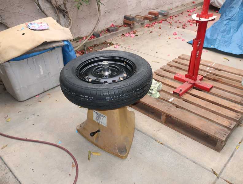
It was also, of course, balanced.
Finally, it was packed away in the trunk, never to be seen again. Or, so we can hope.
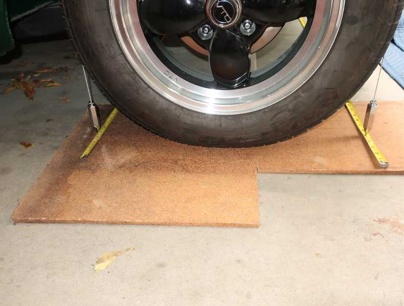
Wheel Alignment
I have always done my own wheel alignment on cars I've restored, my Porsche 912 and MG TD. It takes some care but is otherwise straightforward. If you search a bit, you can find all kinds of ways to align wheels at home. Here is my procedure.
First, the car must be dead level in the lateral direction. Some slight longitudinal slope is OK, as we are not setting caster. If we were, the measured caster would have to be corrected for the slope of the floor.
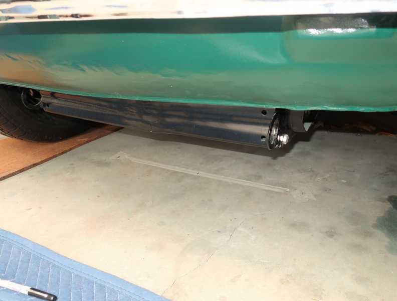
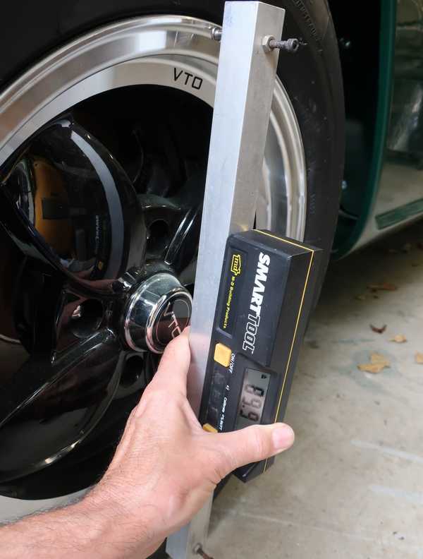
I checked the floor's slope with a long, precise piece of square aluminum tube and an electronic level. I use these for various purposes, and they can be seen in the frame-alignment section. I measured 0.5 degree slope and leveled the car by placing pieces of 3/8-inch plywood under both right-side wheels.
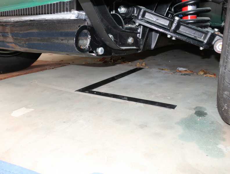
To set the camber, the wheels must be precisely in the straight-ahead position. Setting them by eye is not accurate enough. To center them, I needed a datum marking the center line of the car. To draw the datum, I first dropped plumb lines from well-defined points on opposite sides of the frame and marked them on the floor. Next, I drew a line between them, found the halfway point, and used a large carpenter's square to draw a perpendicular line, the datum. I then extended the line as far forward and rearward as I needed.
I set the steering to the center of its range. I measured just under three turns, lock-to-lock, so the center was a sparse 1 1/2 turns from either extreme.
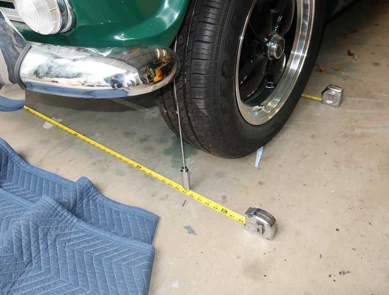
I placed plumb lines over the front tires, inserting the strings into narrow grooves on the tires. I used the toe-in adjustments (screwing the tie rod into or out of the tie-rod ends) to move the wheels to center, so the distances from the plumb lines to the center datum were the same. I then set the toe-in roughly and repeated. With a couple tries, the wheels were centered in the steering range and pointed straight ahead.
When the wheels were precisely straight ahead, I measured the camber. Again, I used a piece of square aluminum tube and my electronic level. The tube has 1/8-inch wall thickness, so it is very rigid. Screws hold the tube a precise distance from the wheel. (There are two sets of screws to accommodate wheels of different sizes.)
As with many cars, the TR's camber is adjusted by inserting or removing 1/16-inch shims between the lower suspension-arm mounts. When I received the car, it had three more shims on the right side than on the left; this time, it needed two more on the right. That's not unusual. The spec for camber is plus or minus 0.5 degrees from vertical; the final setting was 0.3 degrees on one side and 0.2 on the other. One shim changes the camber ~0.4 degrees, per my calculation, so this was about as close as I could get.
Finally, I adjusted the toe-in. This adjustment required care, but it was straightforward. With the plumb bobs hung over the tires, I measured the distances between the front and rear with measuring tapes. Since the toe-in had already been set roughly, the adjustment at this point was only minor. I ended up with 1/16-inch toe in, a good value.