![]()
Brakes
When I received the car, the brake and clutch hydraulics were set up to use DOT5 fluid. Although the DOT5 does not harm paint, there was considerable paint damage from the earlier use of DOT3/4, resulting in rust. All had to be repaired. I chose to return to DOT3 and to replace all of the hydraulic parts. Of course, after half a century, the brakes themselves needed a bit of attention, too.
Click on any picture to see a larger version in a new window.
Contents
Pedals and Master Cylinders
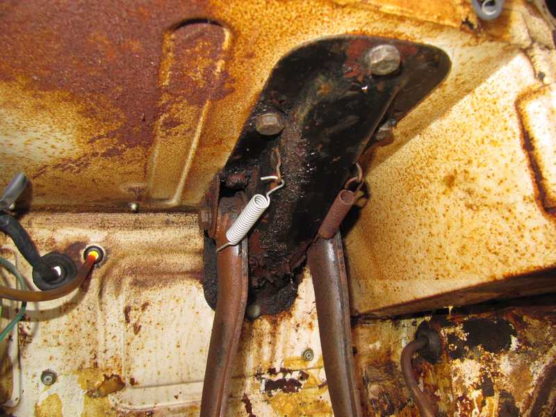
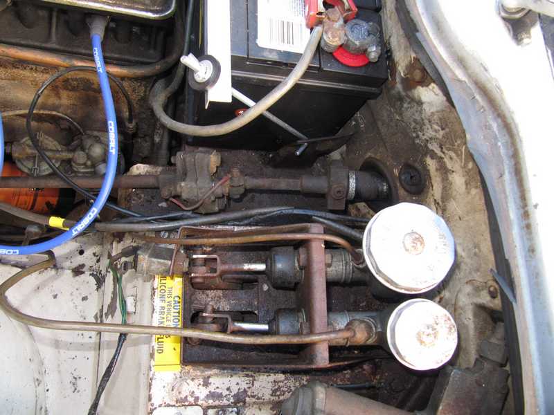
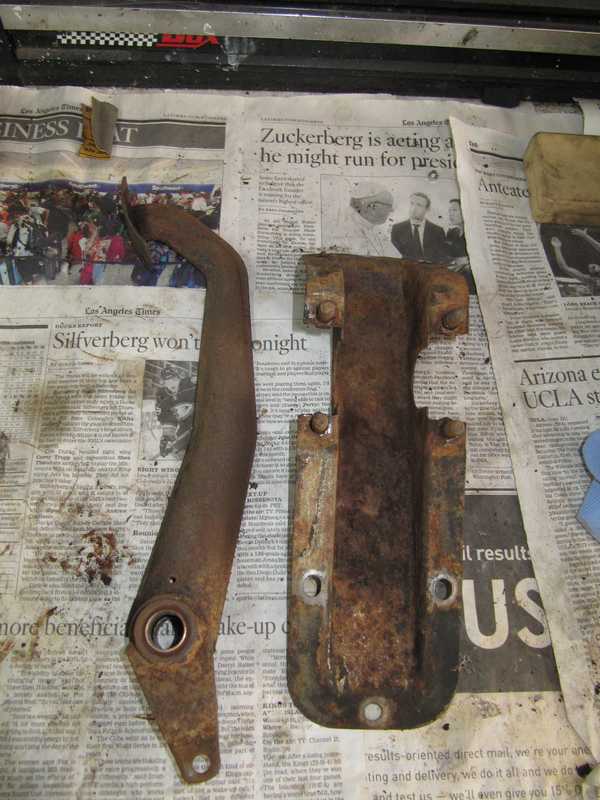
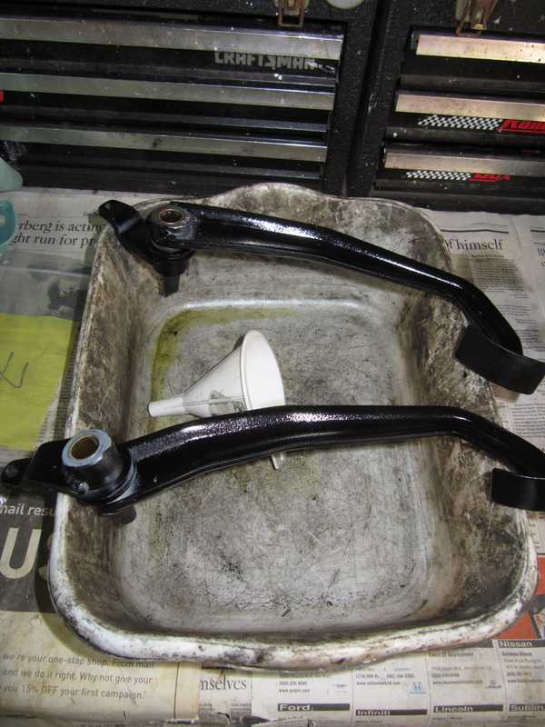
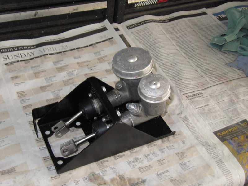
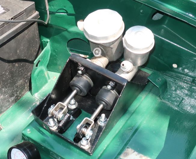
The pedal and master cylinder assemblies were pretty grody: brake fluid had taken off most of the paint and rust ensued. The mounting bracket for the clutch and brake master cylinders was similarly nasty, but, like the pedal parts, not beyond redemption. Below, the assemblies in the car and on my workbench.
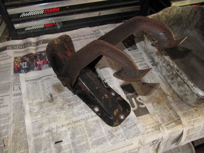
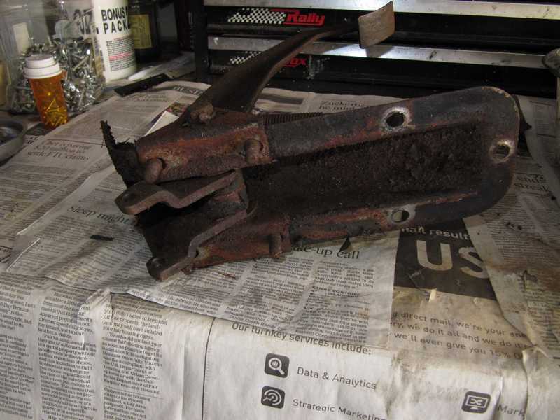
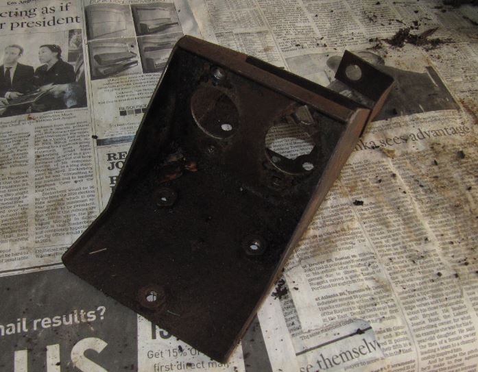
The parts below have been cleaned in solvent. A lot of the paint peeled off in the process.
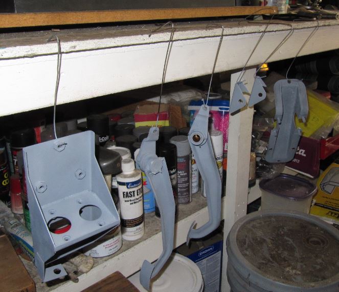
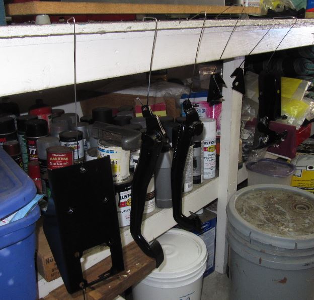
I used phosphoric acid rust remover to clean up the pedal parts, plus some work with sandpaper and a wire wheel, where it could be used. (Abrasive blasting would have been best, but I don't have a blast cabinet.) I washed the parts, then primed and painted them with my engine paint, which has good brake-fluid resistance. (I tested it.) Below, the parts are hanging from the edge of my workbench as they dry.
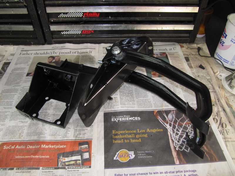
The studs--really welded screws--on the pedal-mounting bracket had to be replaced. I just cut off the old ones and welded on new ones. I did that before the bracket was painted, of course.
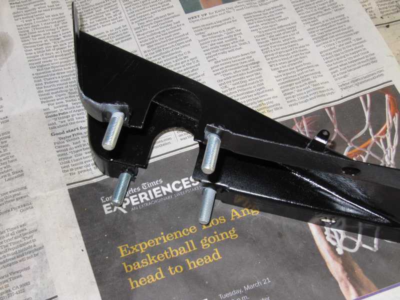
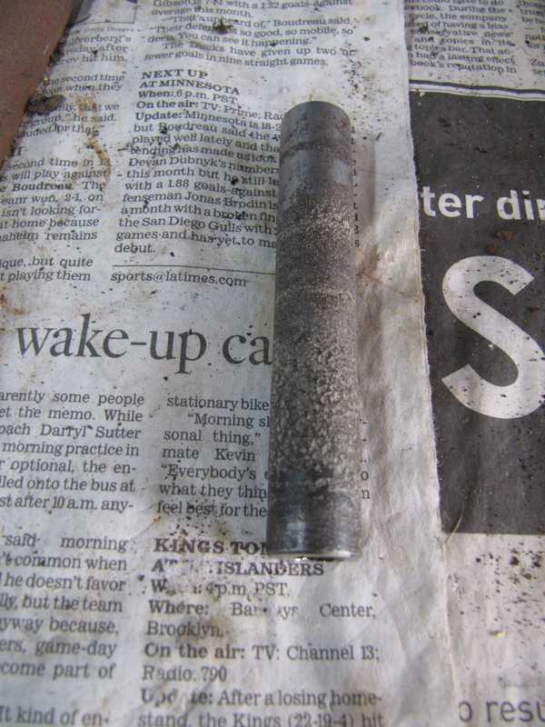
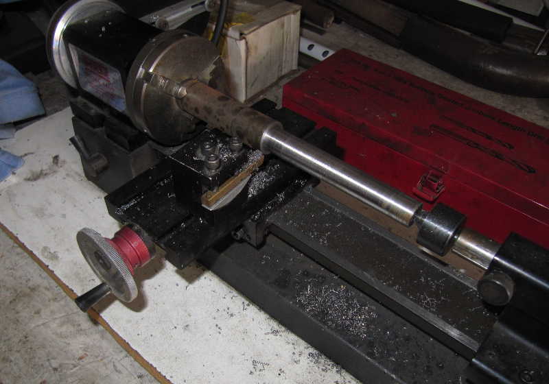
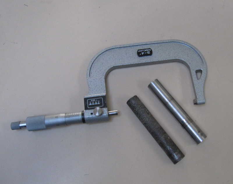
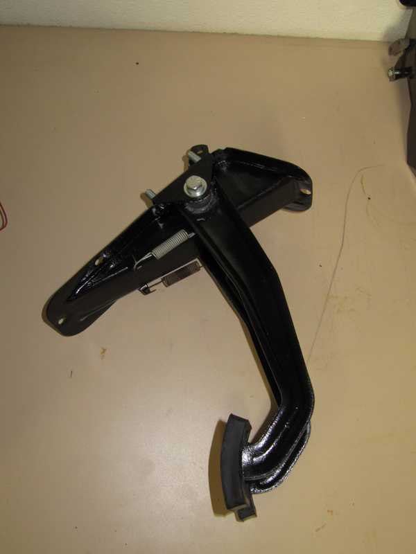
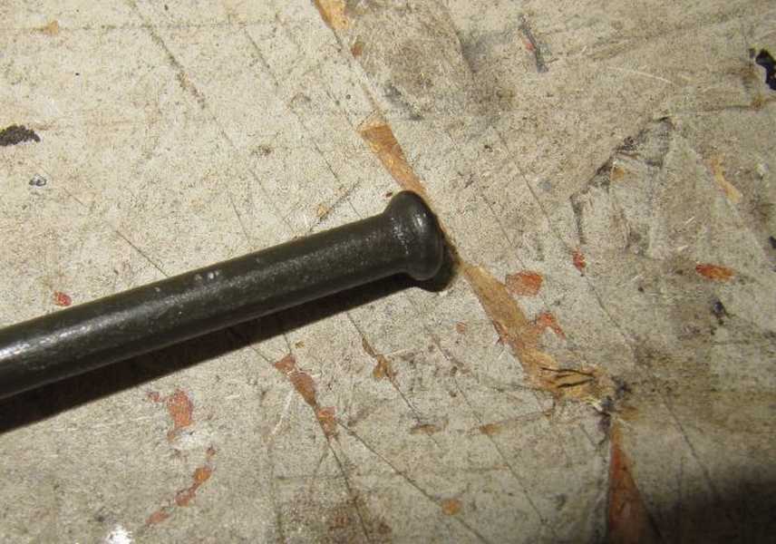
The pedal shaft was a goner; it was badly corroded. I'm surprised it didn't chew up the bronze pedal bushings, but they showed only a few mils of wear. Instead of buying a new shaft and pedal bushings, I made a new shaft, 2-3 mils oversize to accommodate the wear in the existing bushings. It's easy to make; it's just a 0.625-inch diameter steel cylinder, 3.630" long, with 3/8 UNF threaded holes at each end. The new shaft is a smooth, sliding fit into the pedal-arm bushings.
The sintered bronze bearings are porous. Before they are installed, they are soaked in oil for a day, leaving them (supposedly) lubricated for life. I found various opinions, probably none of them informed, about the possibility of relubricating the bronze bearings. So, as an experiment, I tried plugging one end of each shaft opening, filling it with oil, and leaving it for a day. Typically, when new bearings are oiled in this manner, the oil displaces air in the bearing and bubbles appear at the bearing's surface. I saw no bubbles, indicating that (1) the bearings still contained oil, (2) the pores were closed up by use, or, most likely, (3) a little oil was absorbed, but not enough to create visible bubbles. Whatever the situation, I drained the oil and assembled the pedals. In any case, the demand on the bearings is not great, so their lubrication just doesn't matter all that much. The last two pictures show the completed pedal assembly.
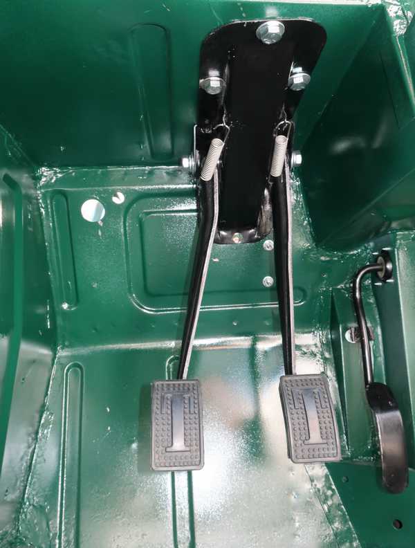
After a couple years of other work, the car was ready for the installation of the assembly.
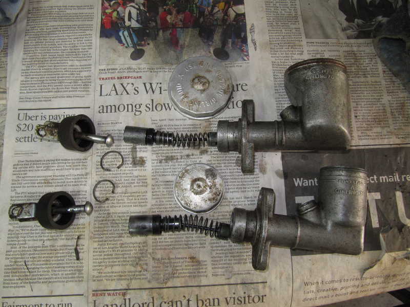
Master and Slave Cylinders
The brake and clutch master cylinders came apart easily. Their bores looked good. I was a bit more concerned about the clutch slave cylinder, as it had been leaking, but its bore looked almost as good as the others; I gave it a light honing and a once-over with 600-grit sandpaper. I first cleaned the parts with solvent; I then cleaned the outsides of the bodies with a brass wire brush and ammonia. (Ammonia does a good job of removing oxide from aluminum, thus brightening it.) Finally, I prepared some of the small steel parts for replating.
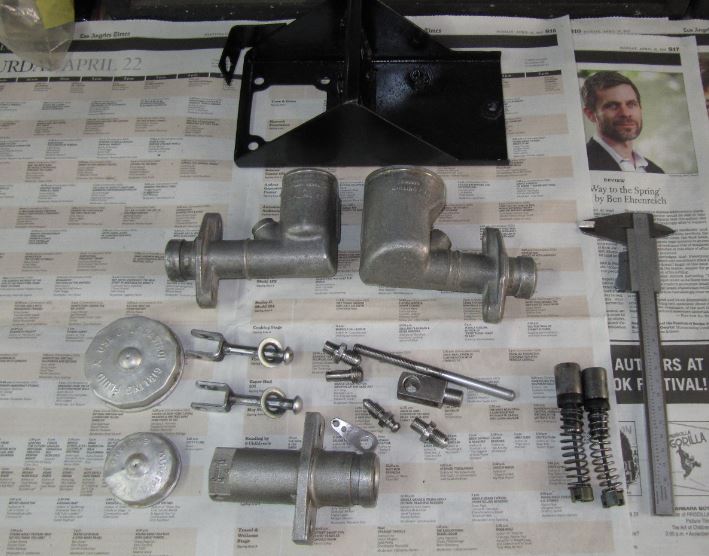
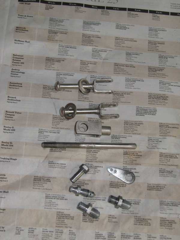
I replated the actuator forks with with nickel, as that was their original finish. I zinc-plated the rest of the pieces. The hanger plate for the clutch slave cylinder's return spring was worn, so before plating it, I welded the hole and redrilled it.
Since the bores were good, rebuilding the cylinders was a simple, cheap job. Below are all three cylinders, completed, and the clutch and brake master cylinders installed in their mounting bracket.
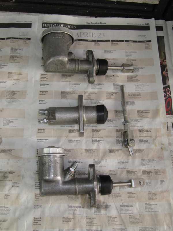
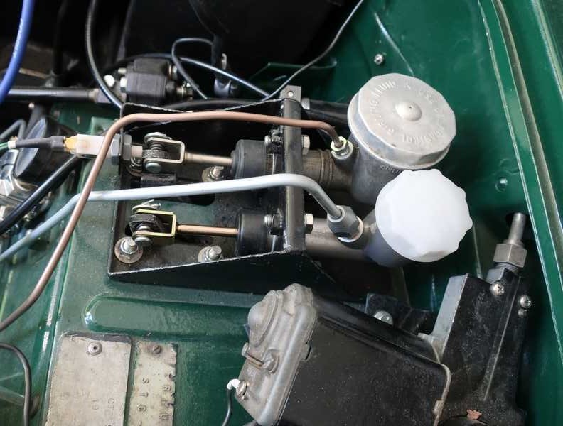
Much later, they were installed on the car.
Sometime after that, I set to the task of bleeding the clutch and brake hydraulics. The brakes went fine, but the clutch didn't. It appeared that the piston was frozen in the master cylinder. Nothing to do but remove the master cylinder and try to fix the problem.
According to the shop manual, it's impossible to remove the master cylinders individually; you must remove the whole assembly. The problem is the master cylinders' lower mounting screws, which are virtually inaccessible. With skinny fingers and a good assortment of sockets and adapters, however, it is indeed possible to remove at least the clutch MC by itself. I was able to free the piston, but the check valve was hopelessly frozen in the cylinder. Reluctantly, I replaced it with a modern repro part.
Front Brakes
Once the bare chassis was in the garage, I couldn't resist taking a look at the front brakes. The pads had almost full thickness and the disks looked good, barring a little rust from sitting around.
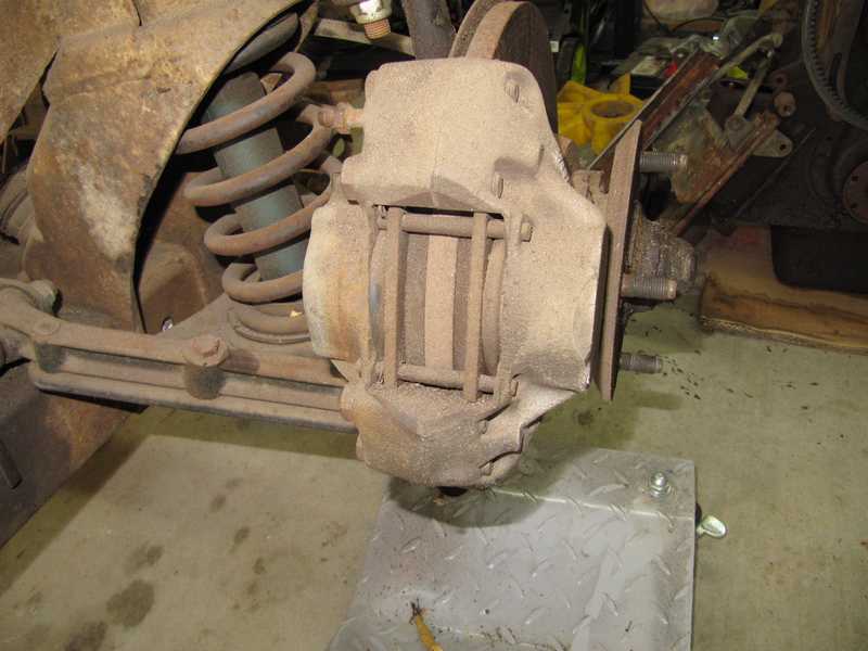
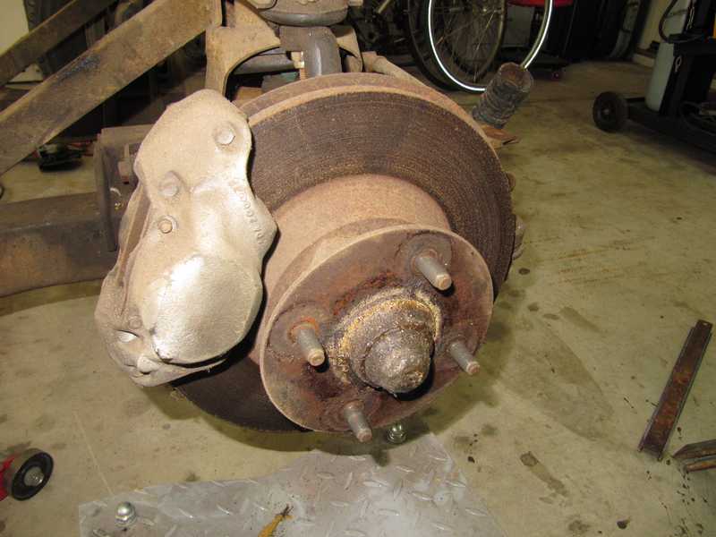
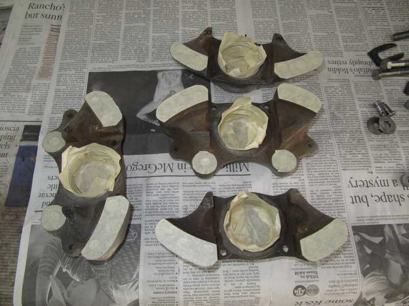
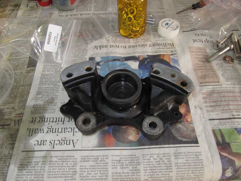
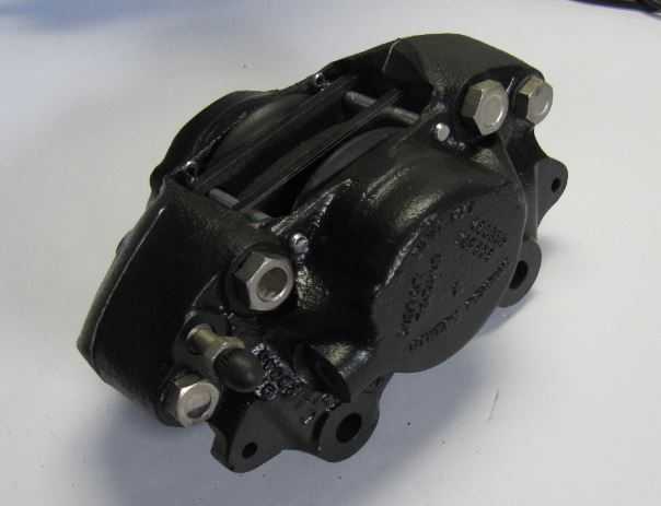
I took the calipers apart for cleaning and inspection. Usually we don't separate the caliper halves for a brake job, but since they probably never had been separated, it seemed prudent to take them apart and check the seals. Fortunately, they were clean internally, and the seals between the halves were in surprisingly good condition.
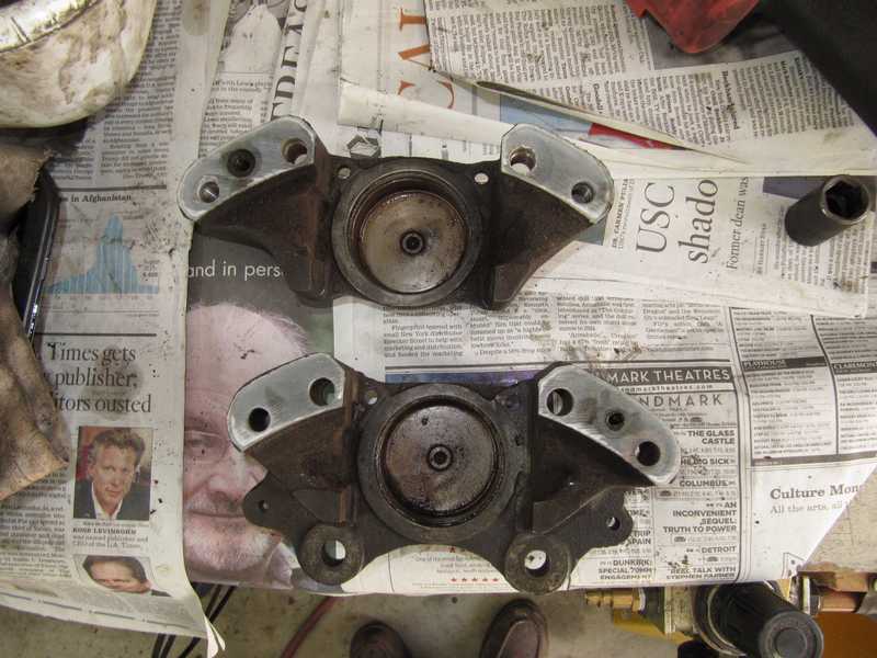
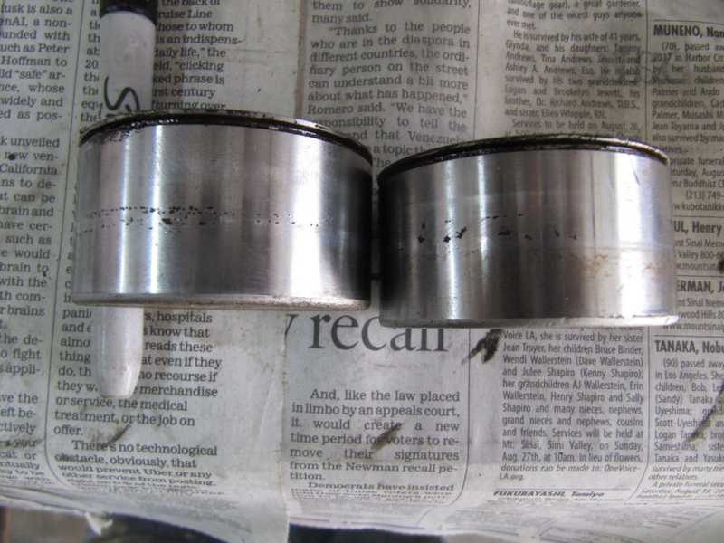
The pistons showed significant pitting. I was amazed that they were not leaking.
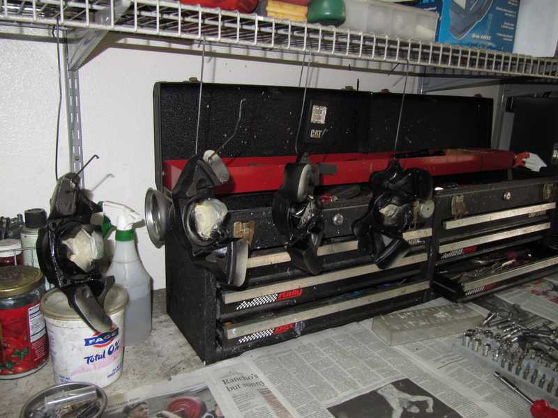
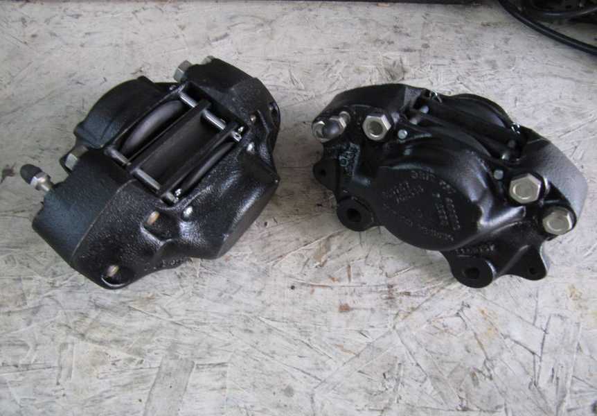
I degreased the caliper bodies, wire brushed them, washed them in detergent, and masked them in preparation for painting. I painted the bodies with VHT caliper paint, a direct-to-metal paint, which withstands high temperatures and resists brake fluid. I hung them from a rack above my workbench to dry.
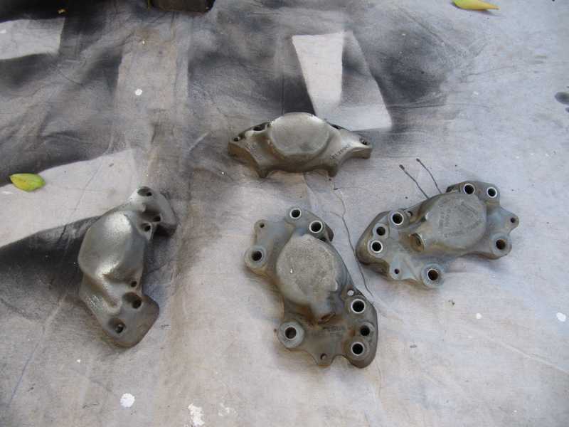
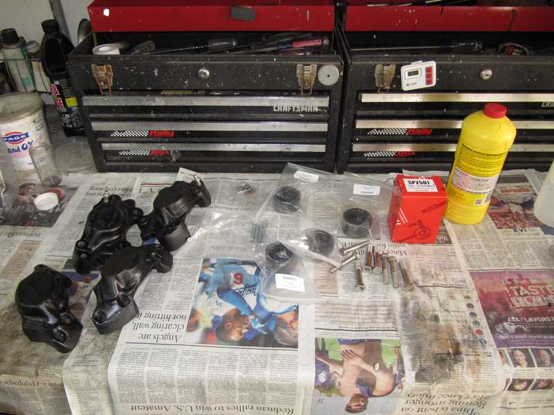
The cleaned and painted caliper halves, along with their new parts, are shown below.
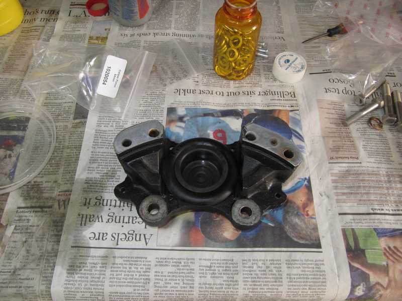
The first reassembly step was to wipe the interior of the hydraulic cylinder with brake fluid to prevent rust. The caliper seal and dust cover were installed first, then the new piston. If I had stronger thumbs, I could have pressed the pistons into the caliper by hand; instead, I used a vise. Care was necessary here, as it's easy to damage the seal.
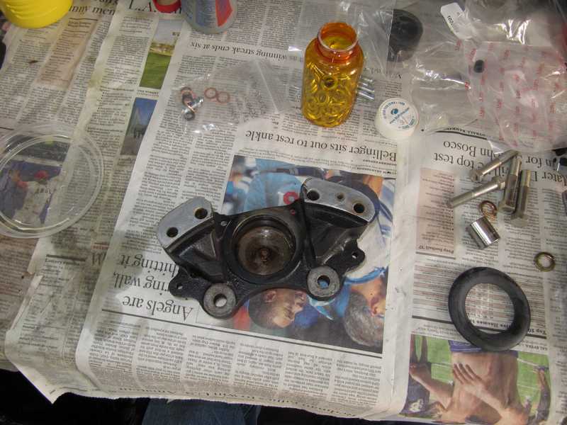
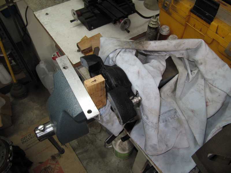
Below, the piston is installed. Because they had been nitrided, the new pistons were dark gray.
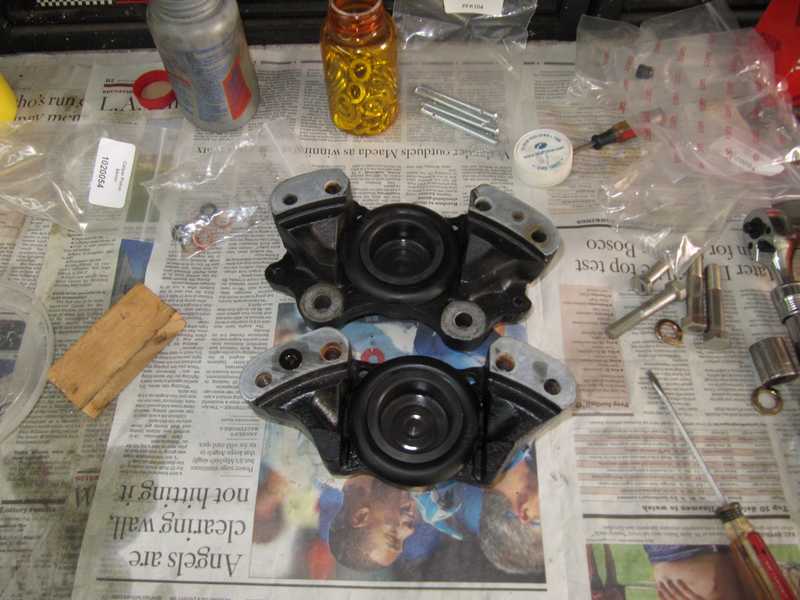
I replaced all the pistons. I installed new seals, dampened with brake fluid, between the two halves. Even though the existing brake pads had almost full thickness, I replaced them with new ones; with brakes, I really want to know exactly what I have. I also installed antisqueal shims, which had been missing.
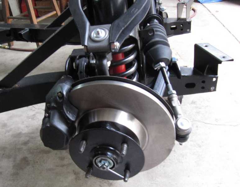
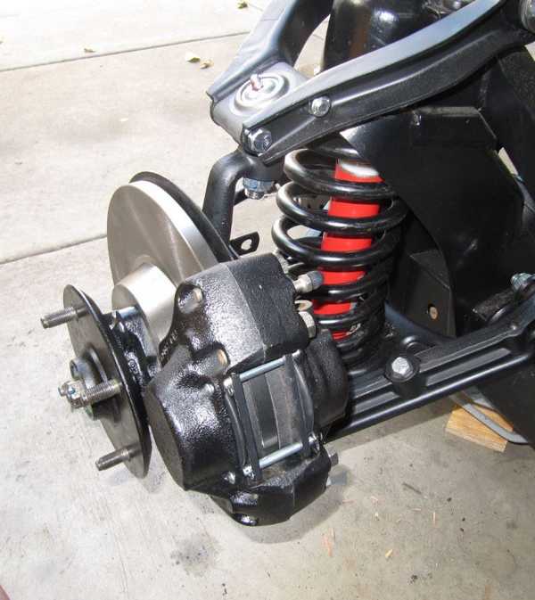
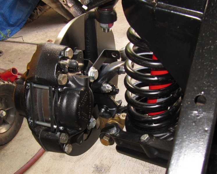
The suspension was restored with new bushings, springs, hub bearings, ball joints, tie-rod ends, and Koni shocks. I installed new disks, even though the old ones could have been resurfaced and reused.
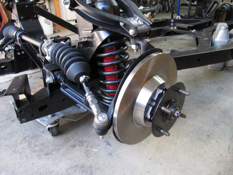
Since the calipers were ready to go, installing them was straightforward. You may notice that I haven't bent the split pin for the axle nut yet; I'll finish it when I'm sure I won't have to take the hub off again.
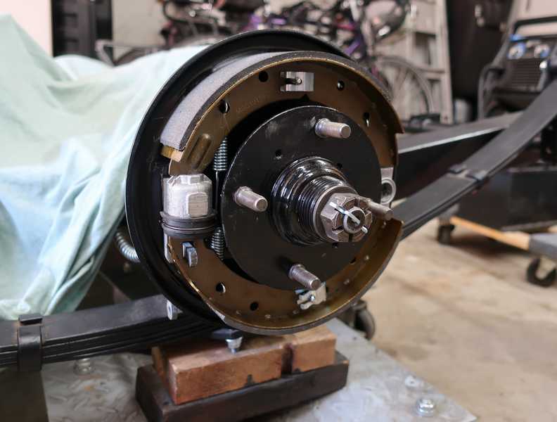
Rear Drum Brakes
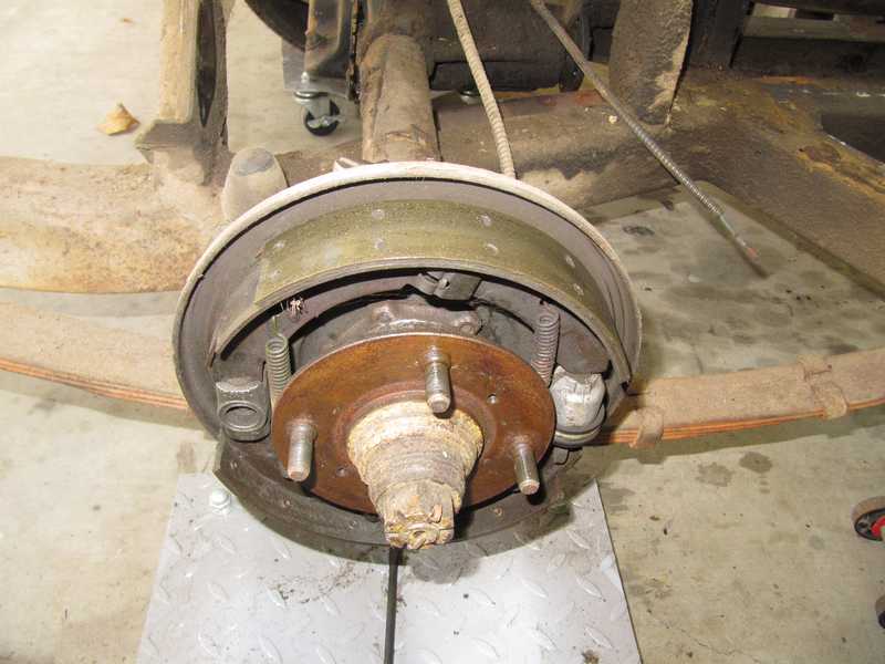
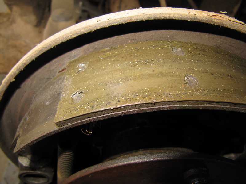
The rear brakes were due for replacement, as a couple of the shoes were worn down almost to the rivets. (The fact that the car had riveted brake linings was, by itself, evidence that they were very old; I haven't seen new, riveted shoes for decades.) The right shoes were contaminated with rear-axle oil, not a big surprise on a car this old; the left side also had signs of leakage, but it had not contaminated the brakes. The drums' braking surfaces, however, were still smooth, so I could continue to use the drums.
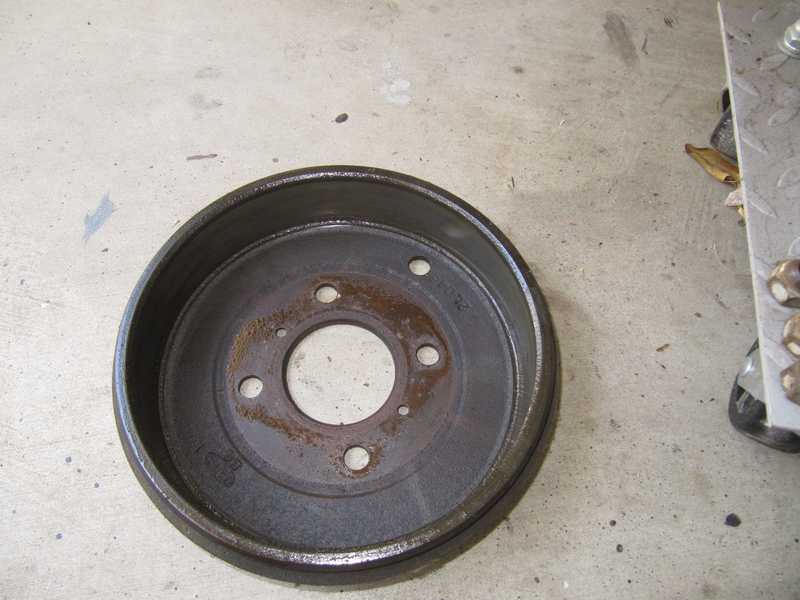
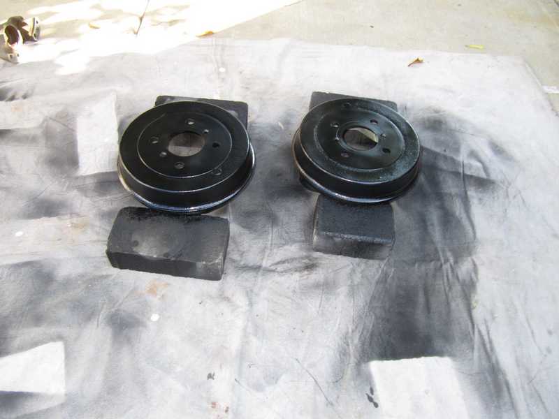
Restoring the drums was straightforward: degrease with solvent, remove the rust with a rotary wire brush, wash in strong detergent, and spray them with the same paint used for the brake calipers. I didn't have them resurfaced, as they simply did not need it.
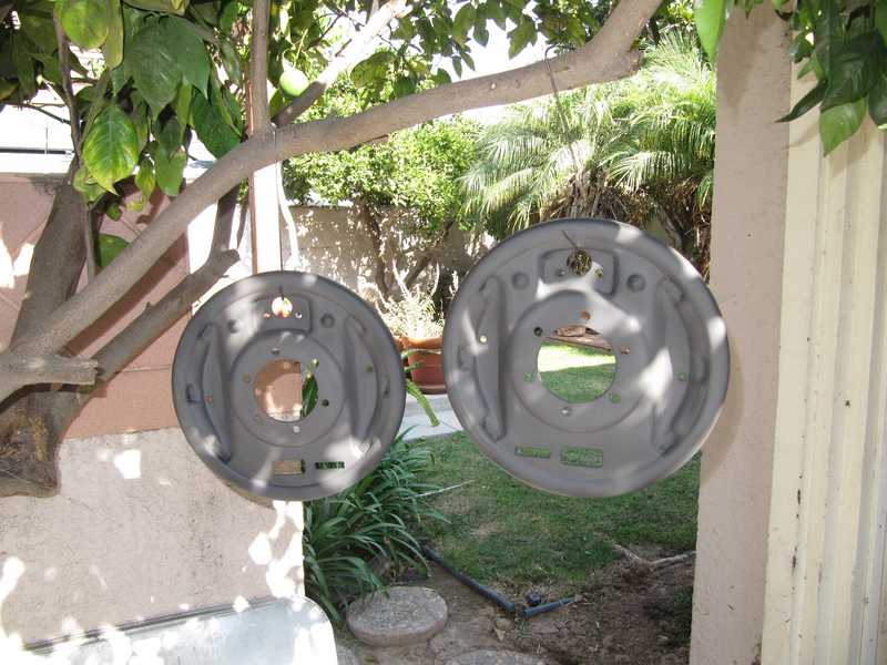
The backing plates were grungy but not rusty. I cleaned them in solvent, wire-brushed off all the old paint, washed them in alcohol, and gave them a coat of primer. I hung them from the orange tree to dry.
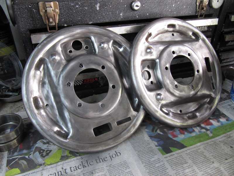
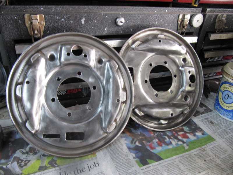
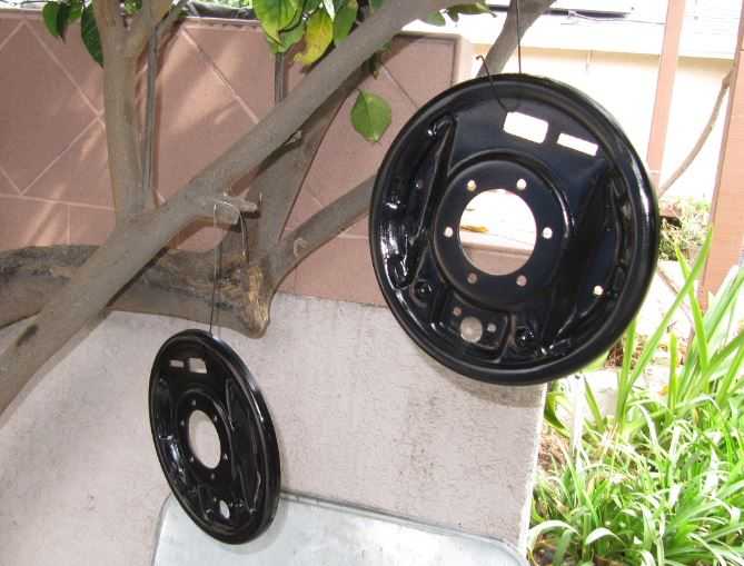
I had a little paint left over after painting the frame, so I sprayed two coats of semigloss on the brake backing plates, completing their restoration. I stored them in plastic bags for several months until I was ready to install the brakes.
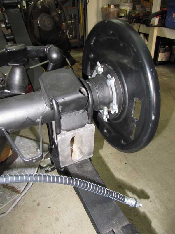
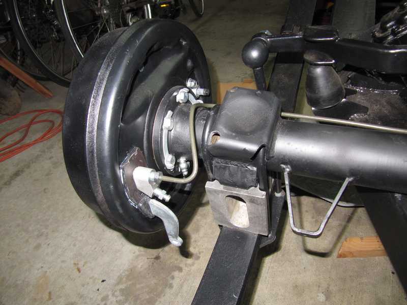
The first step in reassembling the rear brakes is installing the plates on the axle tubes. The axles, greased hub bearings, and bearing housings must be installed at the same time as the plates. Shims are used to set the axle end float; more about that here. Below, the left-side plate mounted on the rear axle. I didn't bend the lock tabs until I was sure that I would not have to disassemble anything.
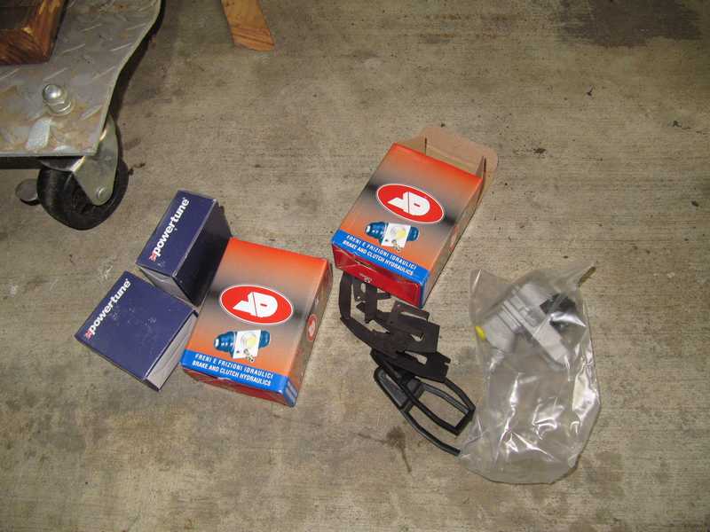
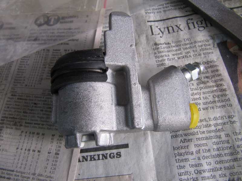
I bought new wheel cylinders, adjuster blocks, and mounting hardware. I probably should have restored the existing wheel cylinders, as the new ones were a little strange. First, they had a pronounced mold flashing, which I had to file off, because it interfered with their ability to slide. Then, instead of the usual sheet-metal clip for the rubber boot, they had cheapo wire clips.
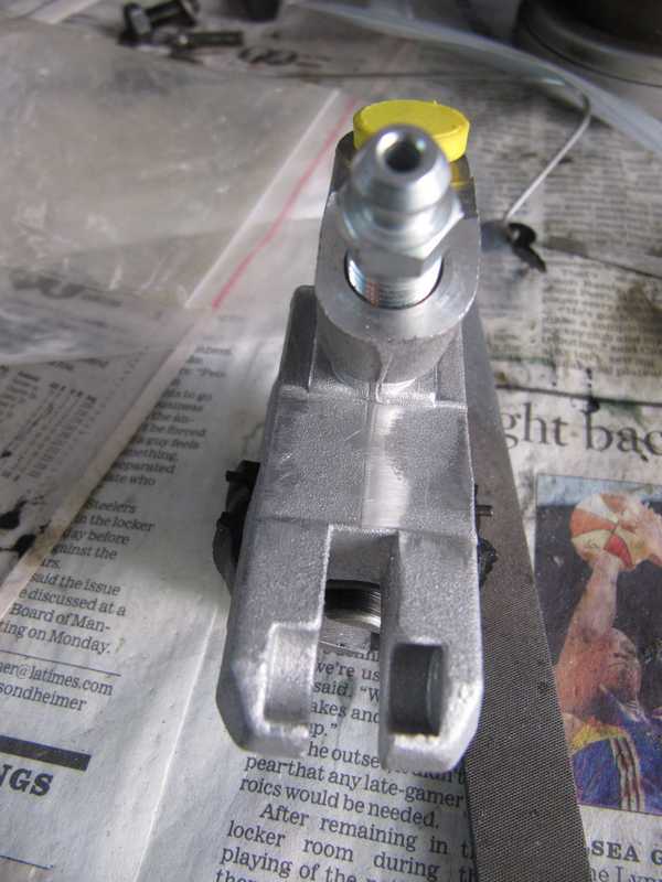
The wheel cylinders are notoriously difficult to install. The Macy's Garage website has a good set of instructions for their installation.
Here's something not generally recognized. Most of us assume that a Girling nut uses a Girling bubble flare. At the rear axle, however, the wheel cylinder requires a 45-degree double flare. The nut supports either kind of flare, fortunately, and the brake hydraulics are a mix of both. But I simply do not understand why this was done.
I hate assembling drum brakes, as it is always tricky to get the springs and clips on, and somehow I always pinch one of my arthritic fingers in the process. But these went together about as easily as they ever do.
The above picture of the original brakes shows the springs on the outsides of the shoes. At first, I installed them that way, simply copying the original installation. The correct way, as specified in the shop manual, is to locate them toward the inside, so I disassembled the brakes and reinstalled them correctly. From what I've seen, installing the springs on the outside is a common practice, probably because it's easier. I doubt that it makes much difference.
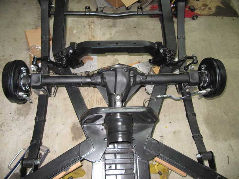
I hooked up the brake hydraulics and final-formed the lines. The rear brakes and suspension were then complete.
Brake Lines
Making brake lines is a clean, fun part of any car project. It's easy and satisfying, and I get to play with my high-end flaring tool.
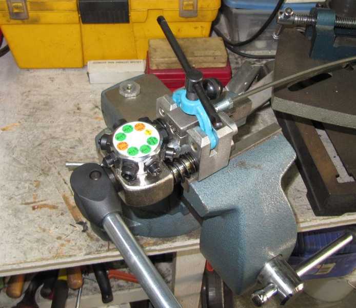
The brake lines in the TR4A use a mix of connectors; most are hooded and use a standard 45-degree flare. In several places, Girling nuts are used, with both girling bubble flares and 45-degree flares. While the old hardware was all SAE, the new parts, for no comprehensible reason, are a mixture of metric and SAE: the hoods are threaded SAE, 3/8-24, but their flats are 13mm. Similarly, the flex lines have metric flats, although the threads are SAE to match the hoods. So, here's the dance: I use a metric wrench to prevent the flex line from turning as I tighten the SAE nut that holds it in place, then exchange the SAE wrench for a metric one to tighten the hooded fitting. Finally, I pick up an SAE wrench and tighten the Girling nut on the other end of the line. Simple and logical, yes?
For the links between the flex lines and the disk calipers, I used Cunifer line, as it makes the tight bends much easier. In the rest of the car, I used ordinary steel brake line material, as it's perfectly adequate and much less expensive. It is, however, harder to form, and its olive covering is easy to scratch. Of course, I used new fittings throughout.
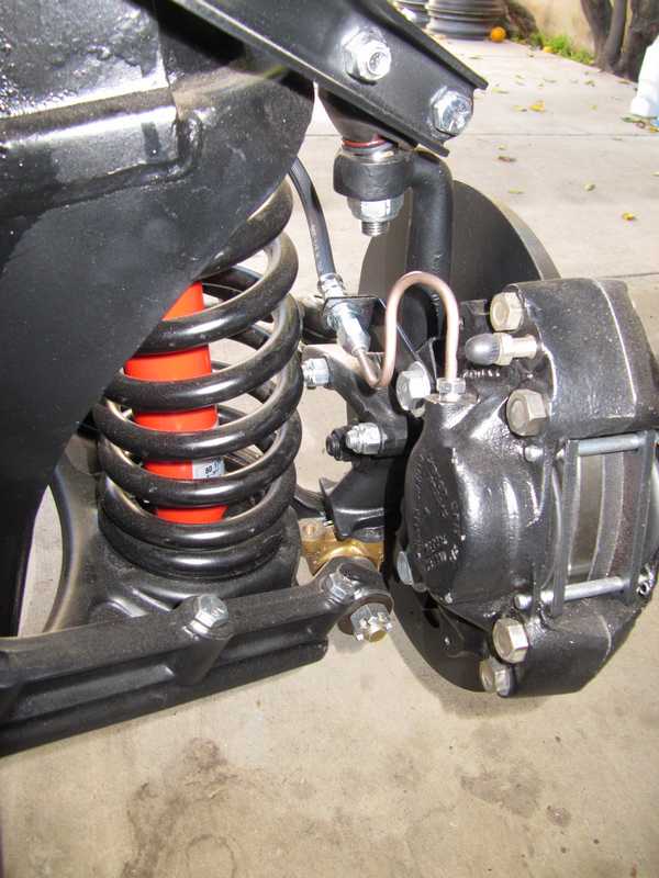
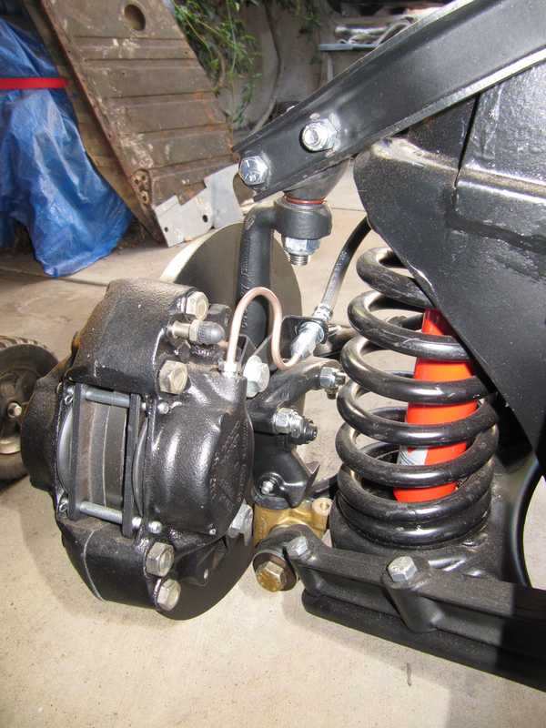
The pictures below show the connections from the front brakes to the brass tee junction.
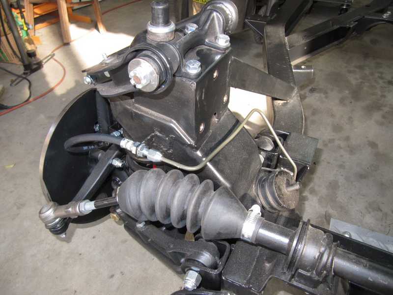
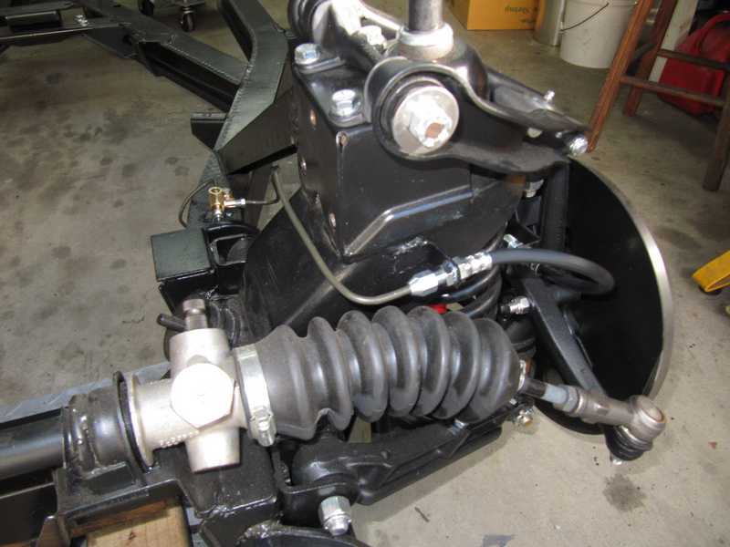
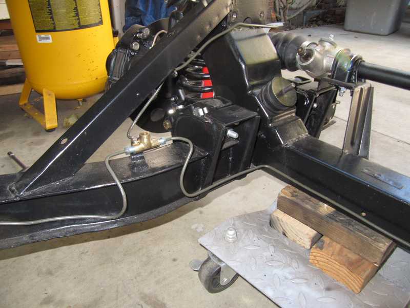
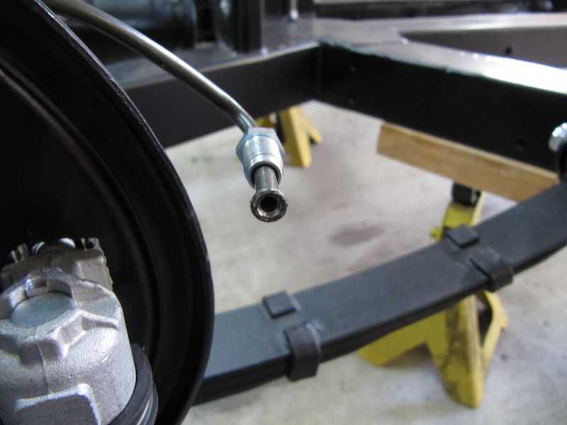
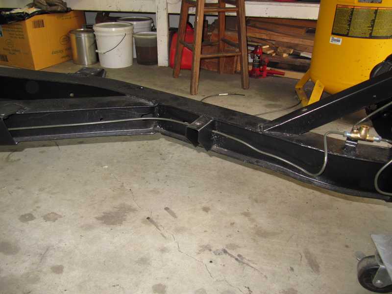
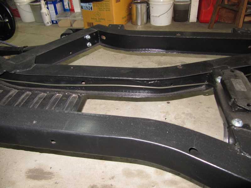
The TR4A has a long line from the brass tee to the rear axle. Originally, there was a union in the middle of that line. I eliminated it, as it's a reliability risk. It's a little tricky, but far from impossible, to run the line without it. Eventually I installed original-type clips to support the brake lines along the inner side of the frame.
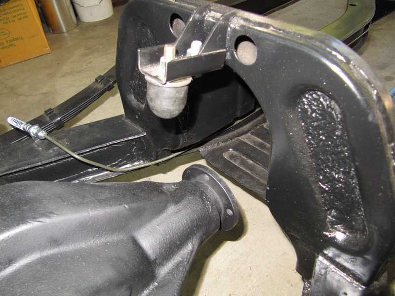
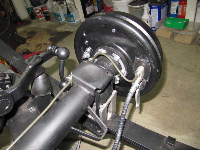
Once the rear brakes were installed, I formed and connected the lines at the rear axle. And, yes, I know that the shock links, as shown in these pictures, are backwards. This is explained here. The links were corrected later.
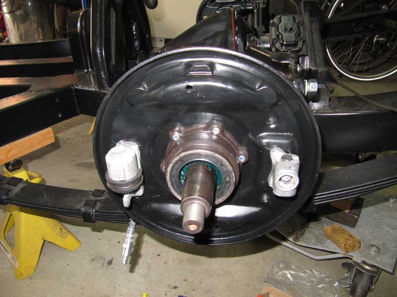
Bleeding the Brakes
The above pictures show a potential problem in bleeding the brakes. The rear brakes have only one bleed nipple, on the right side, which bleeds the entire rear part of the brake system. It seems, however, to be located in the lower part of the brake cylinder, pointed downward. That's a serious no-no; it should be at the top, where the bubbles go. Checking the shop manual and on-line pictures confirmed that this is indeed the correct installation. Note that fluid enters the left cylinder at the bottom, as one would expect, and exits the top.
In spite of this seeming flaw, bleeding the brakes was straightforward. I used the classical two-person method, where one pumps the brakes and the other opens and closes the bleeder, and I obtained the desirable "hard pedal" easily. The channel from the bleeder clearly has a slope, so I suspect that it enters the cylinder near the top. Nothing else makes sense.