![]()
Second Engine
My TR4A came with a second engine, unfortunately in poor condition. Its most immediate problem was seized pistons; the engine could not be turned over. Because of the replaceable cylinders used in TR engines, that's not too much of a problem; in fact, replacing the pistons and cylinders is usually part of an ordinary engine rebuild. A greater problem is more general: any engine that has been allowed to get to that condition probably has other problems, as well. I had to decide whether to rebuild the engine or to part it out. That decision depended on what I found when I tore it down. As it happened, all except the cylinders was in decent shape. I ended up rebuilding it.
Click on any picture to see a larger version in a new window.
Contents
- The Engine
- Disassembly and Evaluation
- Cleaning
- Test Fitting the Cylinders
- Painting the Block
- Internal and External Parts
- Engine Assembly
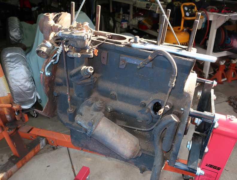
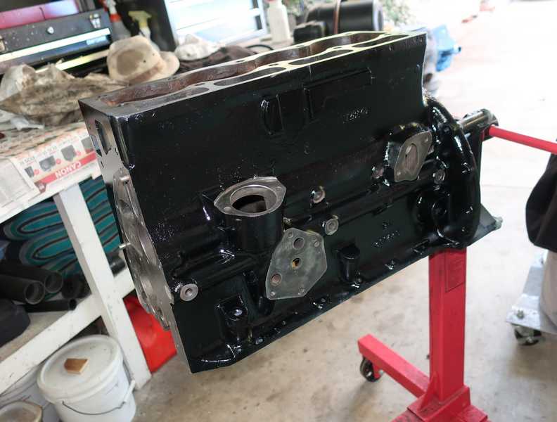
The Engine
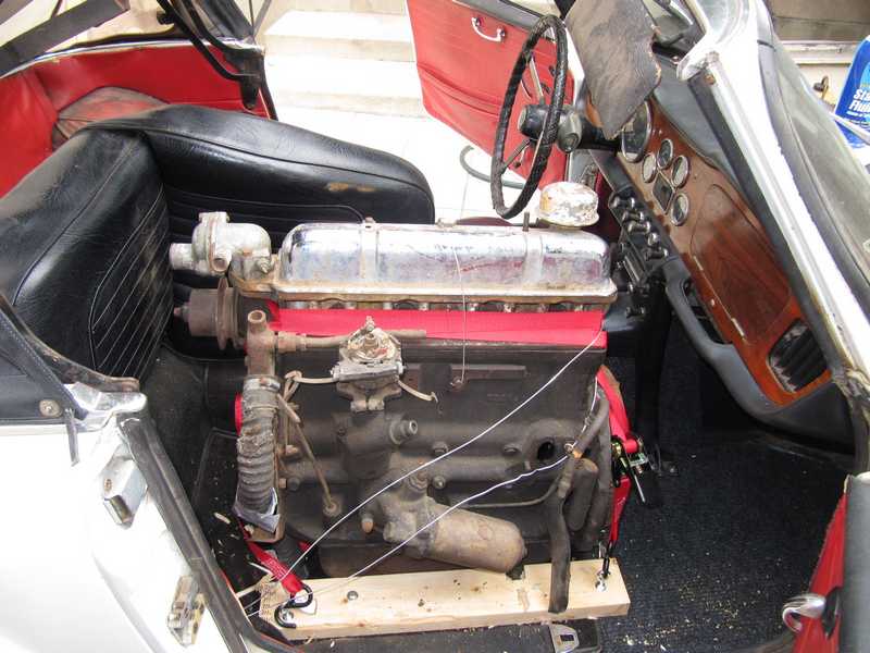
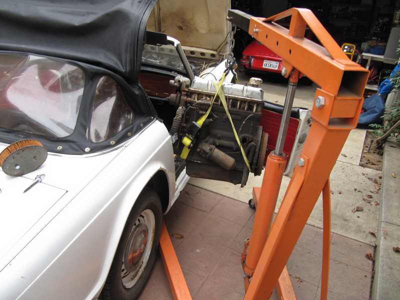
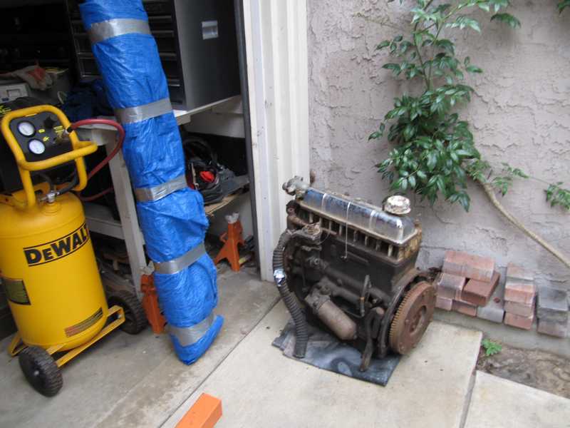
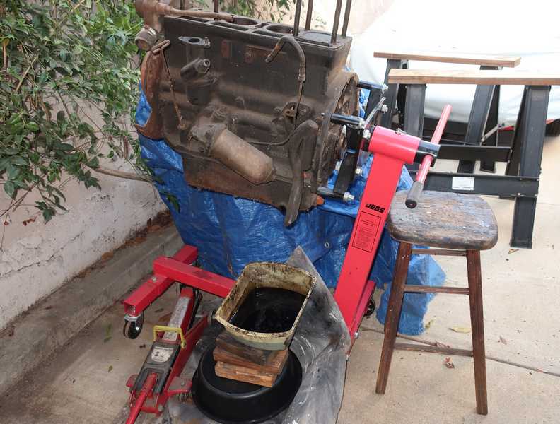
This engine was part of the deal when I purchased my TR4A. It was mounted in the passenger compartment for shipping. I extricated it and set it out of the way, on a pad and under a tarp. There it sat for two years, until I was finally ready to work on it.
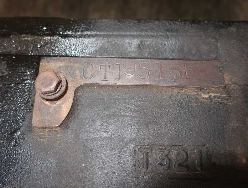
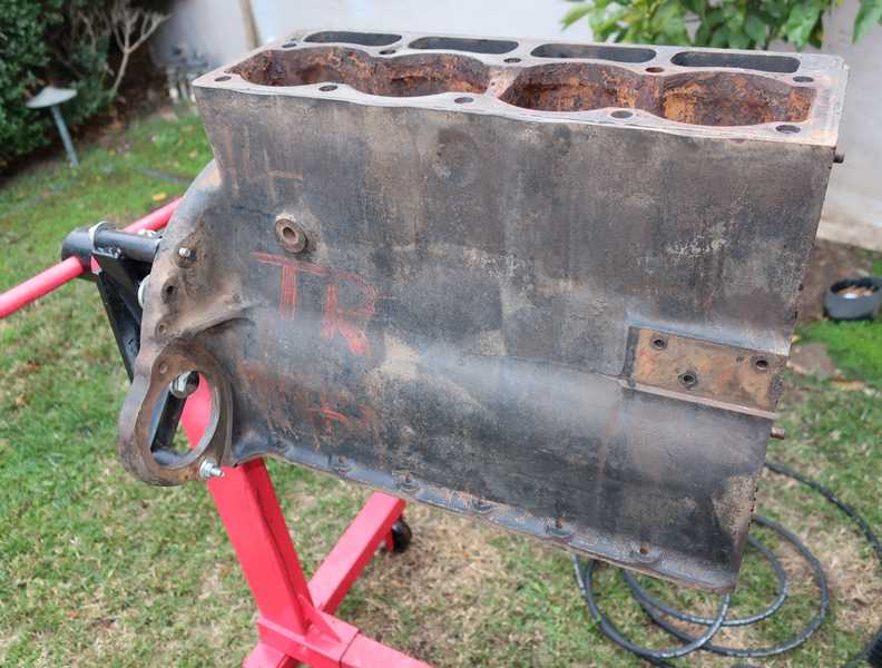
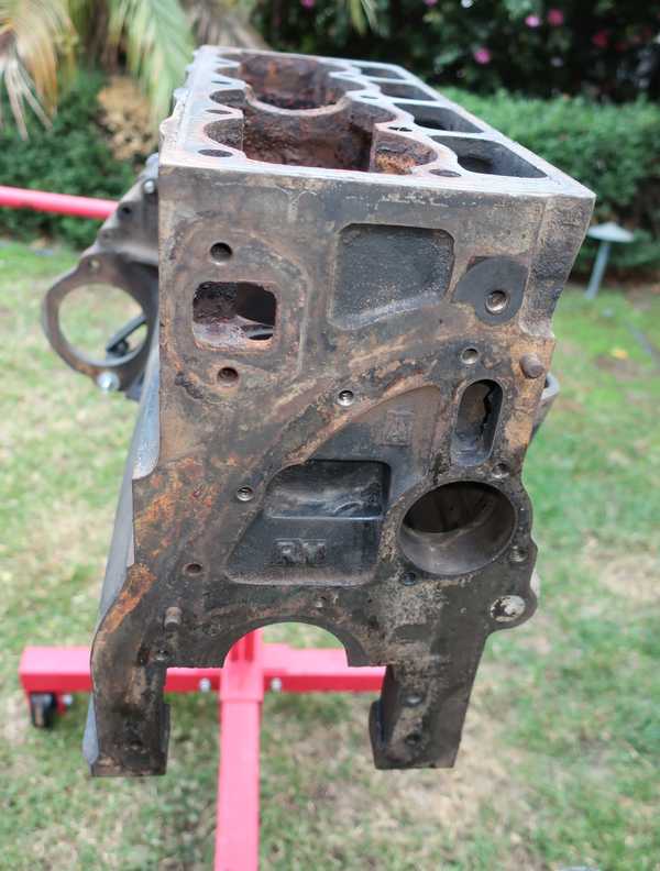
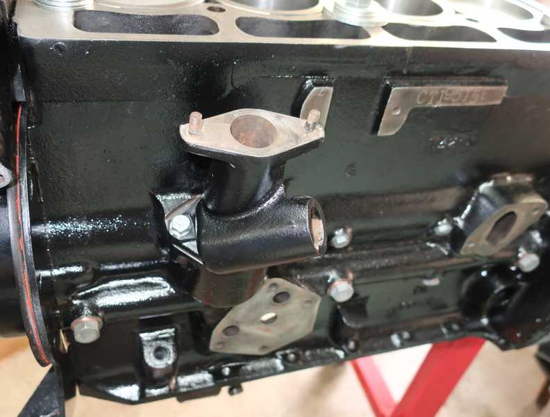
The engine's serial number is CT19515E, making it a TR4 engine from the middle of the production period. Under its crud layer, I found "TR4" painted on the right side. At first, I thought it had been added at a salvage yard, but I later confirmed that it was a factory marking. You can see the markings in old factory photos (e.g., this one, third from the top). I assume that the markings were painted over at some point; I can't believe that the engines were installed this way.
TR4 engines (and TR3s, for that matter) are almost identical to the TR4A engine, so this one should be fine as a spare for my 4A. In fact, this engine provided the cylinder head for my TR4A, as the TR4A's original head was not rebuildable. That left me with no head for this engine, but I can probably find one somewhere.
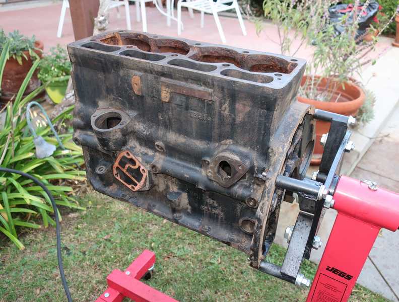
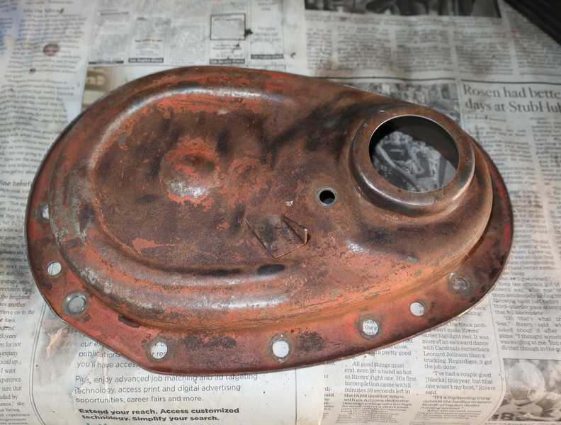
The engine clearly had sat around for a long time before I got it, as it showed paint deterioration and rust. It also was seized; the piston rings were rusted into the cylinders. I added a little Marvel Mystery Oil to the cylinders when I received the engine; it didn't seep out but still didn't loosen the pistons. They were well rusted into place.
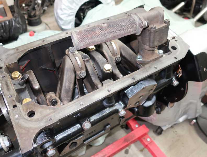
The engine had its original, cartridge-in-a-cannister oil filter and "snorkel" breather pipe. TR4A engines do not have the breather; instead, they have a PCV valve, and the breather hole in the block is plugged.
The options were either rebuilding the engine or disassembling it and keeping or selling the parts. That depended on other aspects of the engine's condition, which required tear-down to determine. Eventually I decided to rebuild it and keep it as a spare.
Disassembly and Evaluation
I drained the oil and gave the engine's exterior a rough cleaning with solvent. The exterior wasn't terribly dirty.
The distributor was still in the engine. It turned out to be a throw-away, as it was internally rusted and badly damaged. It looked like something heavy had hit it at some point, as the body was bent and cracked. It must have been quite a whack; it even cracked the distributor pedestal.
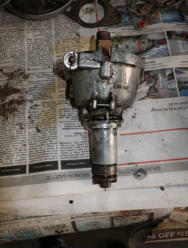
It's no great loss, as distributors and pedestals for this car are cheap and readily available. I simply replaced the pedestal with a good used one.
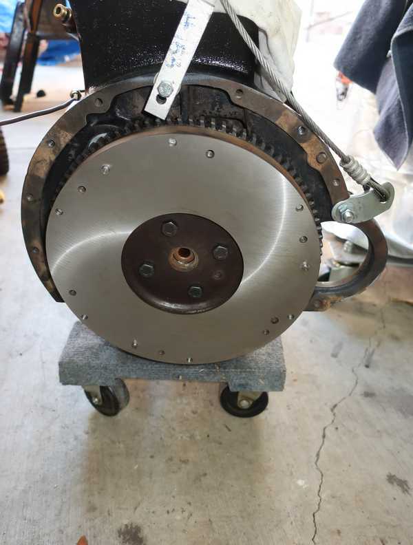
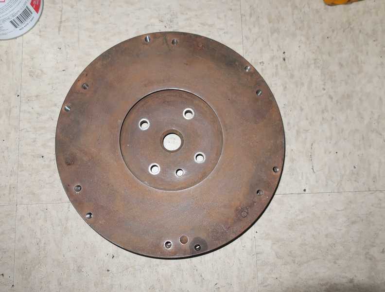
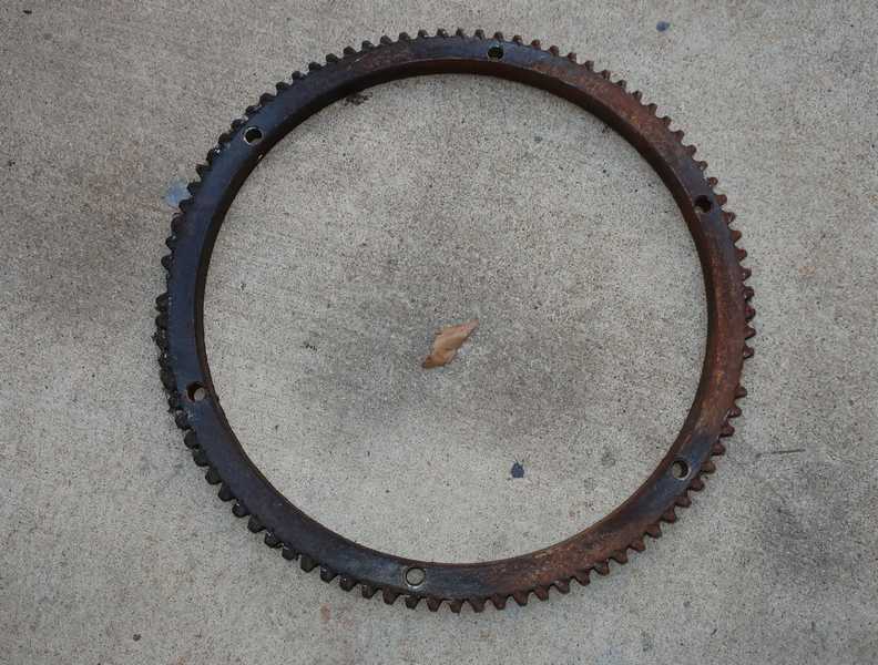
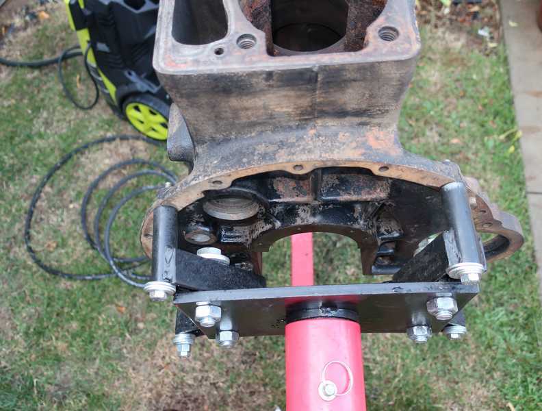
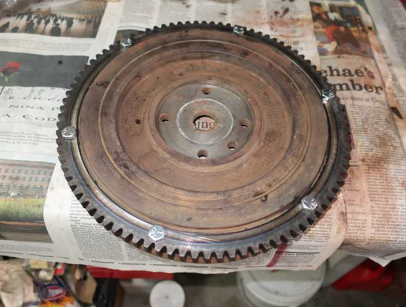
I removed the flywheel and ring gear. The flywheel had some surface rust but was restorable; the ring gear had two missing teeth, so it was trash. I was a little surprised (and pleased) to find that this TR4 engine had a TR4A flywheel. (The three locating pins for the clutch confirm that; the TR4 flywheel has only two.) It probably was replaced at some point so a much superior TR4A clutch with a diaphragm pressure plate could be installed. I had the flywheel resurfaced and balanced, and I installed a new ring gear. The restored flywheel is shown here.
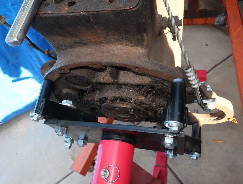
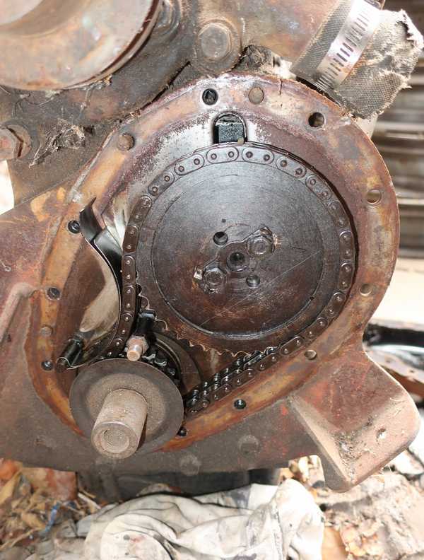
I removed the timing cover and gears. The gears didn't look too bad, but even a little wear in the gears can affect valve timing, so I bought new ones. The elongation of the timing chain was decidedly scary. Between that elongation and the staining of the timing gears, it was clear that this engine had been in use a long time.
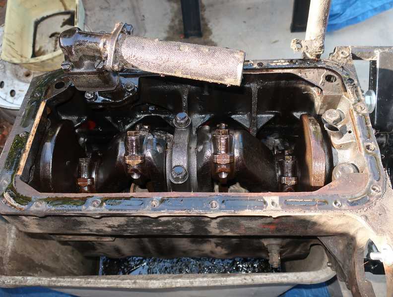
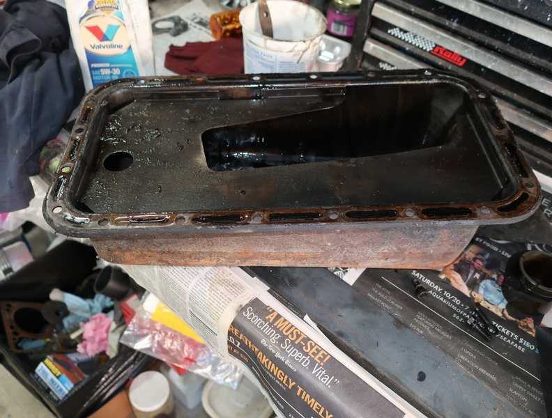
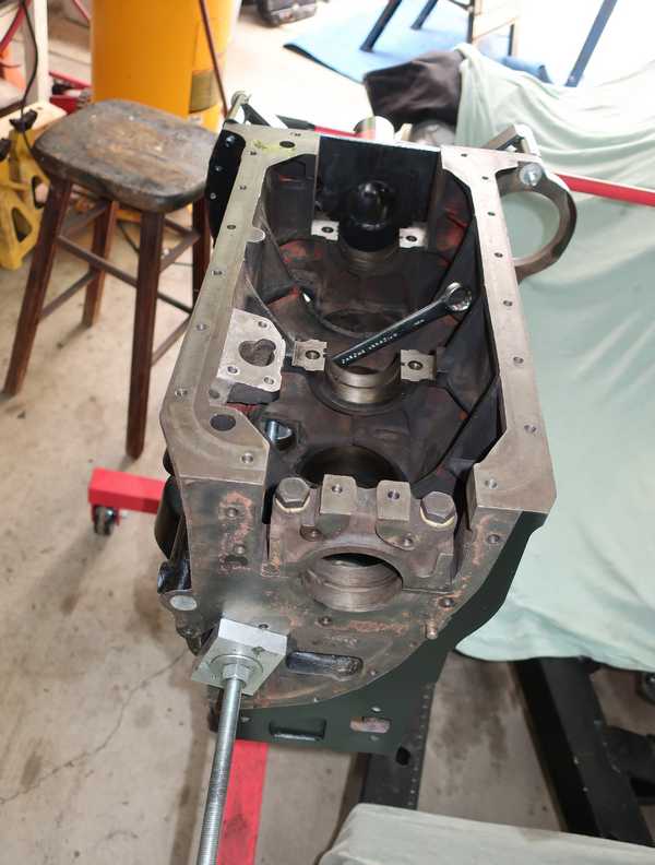
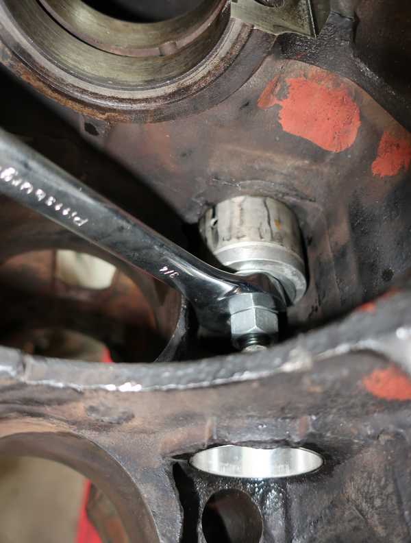
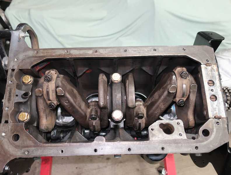
I flipped the engine and removed the oil pan, giving me a first look at the interior. The first surprise: helical spring lockwashers on the connecting-rod stretch bolts. Stretch bolts, when properly torqued, provide enough spring force by themselves to ensure a tight connection; a lockwasher is not needed or desired. Adding a lockwasher creates a couple problems: first, it reduces the amount of thread engagement; second, there is some evidence that split-ring lockwashers don't work in some situations, and the last place you would want to use an ineffective lockwasher is a connecting-rod cap. The issue is controversial; you can find results of Junker tests on-line, indicating that they are superior or inferior to a simple torqued bolt and nut. What I've never found is any analysis explaining those results and showing where spring lockwashers work and where they don't.
From the serial number, this engine's connecting-rod bolts originally had locking plates, but apparently they were replaced in a rebuild. Eliminating locking plates is fine with me; see my rant on the subject. I continued to use stretch bolts, but, of course, bought new ones.
The pan had a half inch of sludge in the bottom. Yuck!
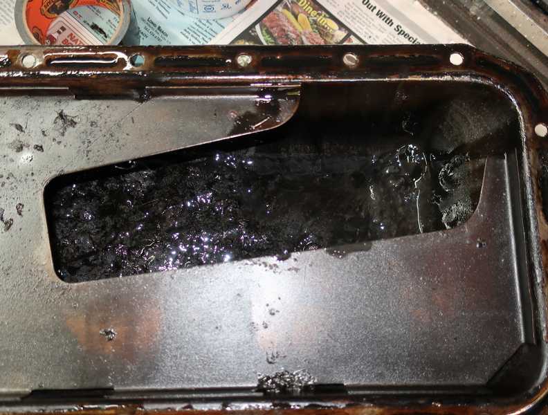
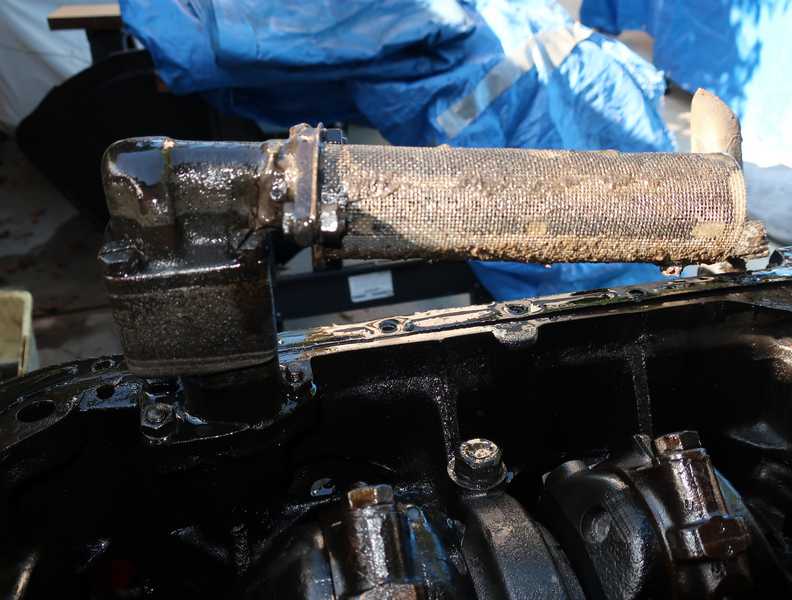
With that much disgusting goo in the pan, it's no surprise that the oil pump sucked up quite a bit of it.
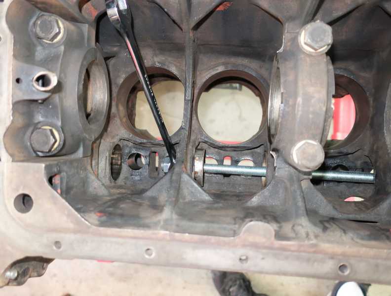
Seized engines usually are not economically restorable, as the cylinders invariably are so badly damaged that they cannot be rebored. Then, the only option is to insert cylinder liners, which often cost more than the block is worth. In contrast, it's easy to be cavalier about a seized TR engine, as the cylinders are replaceable, so it doesn't matter how badly damaged they are. To remove them, however, the crankshaft must be in a position that allows access to the connecting-rod bolts. Fortunately, this engine was left in the ideal crank position, so I removed the bolts easily. If the bolts were not accessible, I'm not sure what I would have done. The only option I can imagine would be to break the pistons with a chisel and to remove the crank and connecting rods together.
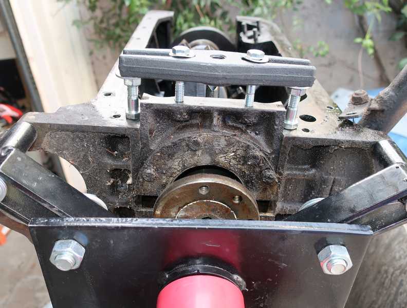
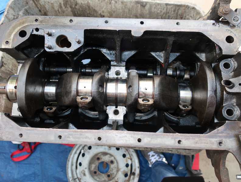
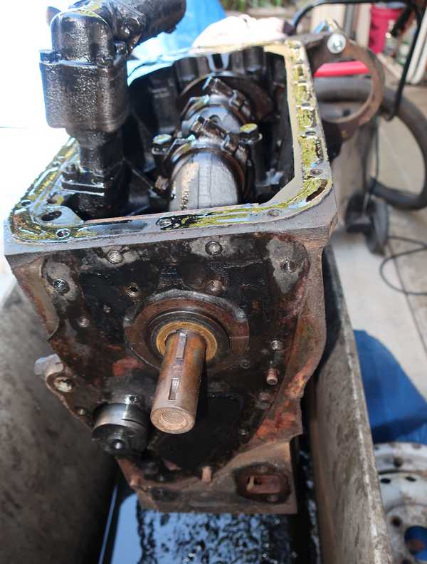
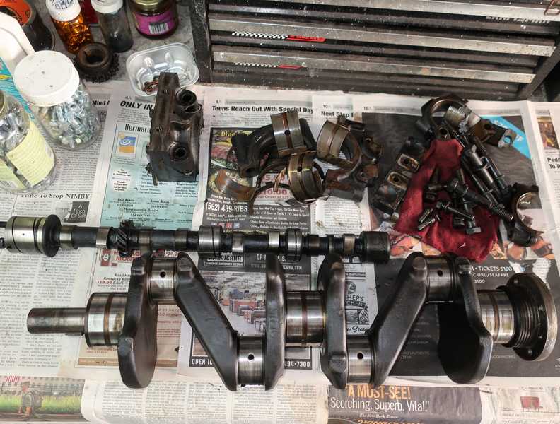
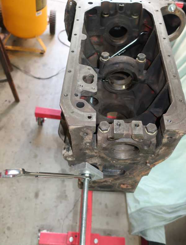
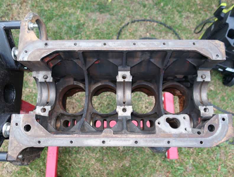
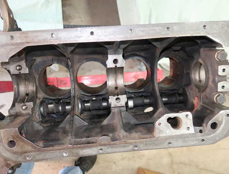
The main-bearing caps required some encouragement, but once they were off, the crankshaft was removed easily. Then, the camshaft was also easy to slide out, probably because the bearings were worn.
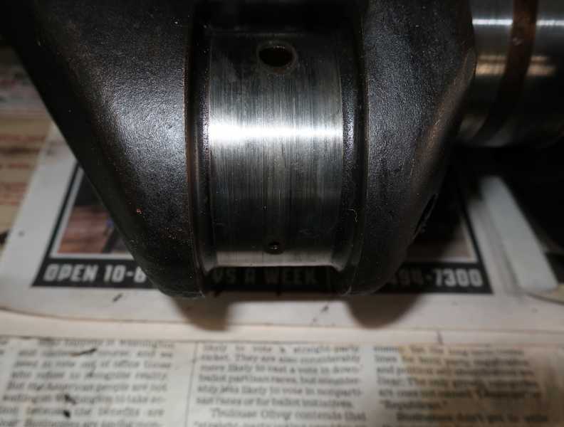
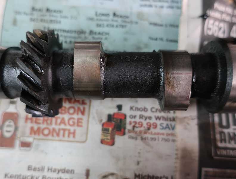
The crankshaft journals showed only light striations, which could have been polished out, but some journals were at the lower edge of their tolerance, so I decided to have the crank reground. I expected that 10 mils would be enough, and it was. The bearings showed normal, high-mileage wear. The camshaft looked perfect; it may have been replaced at some point.
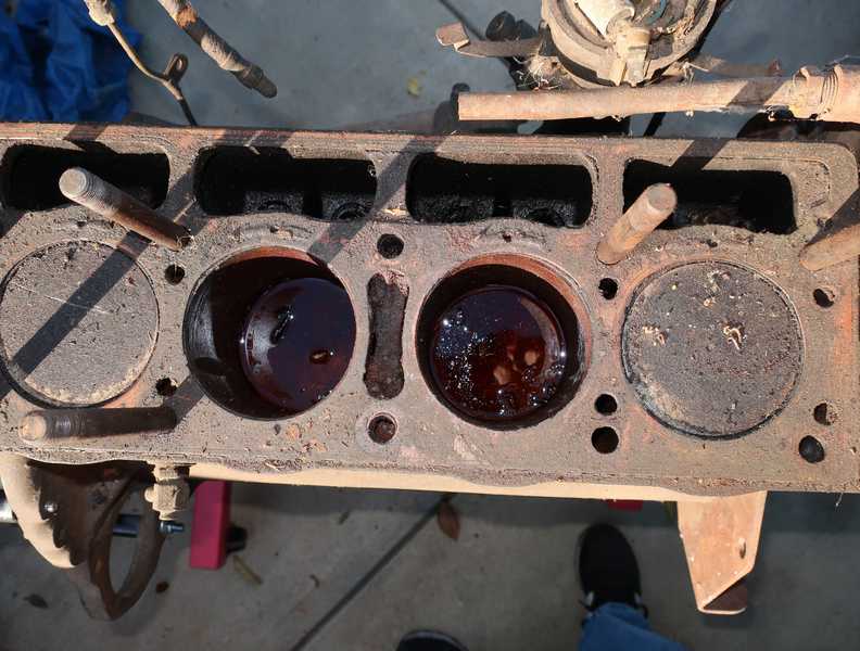
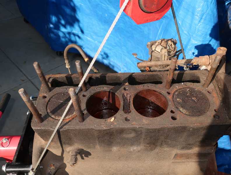
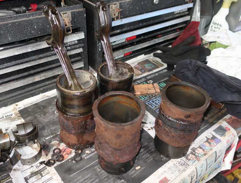
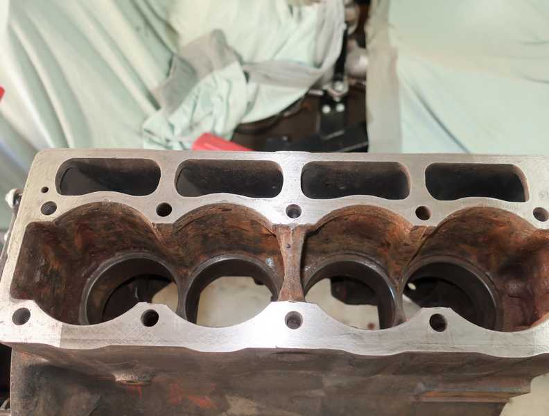
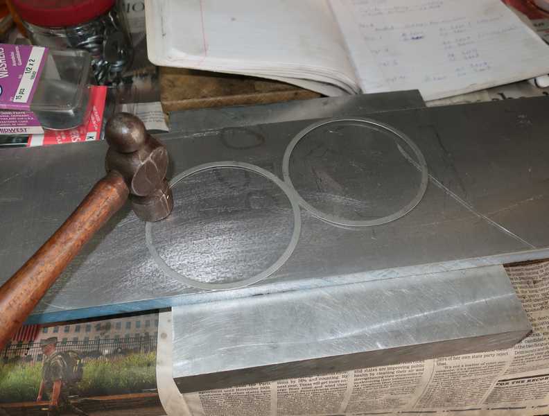
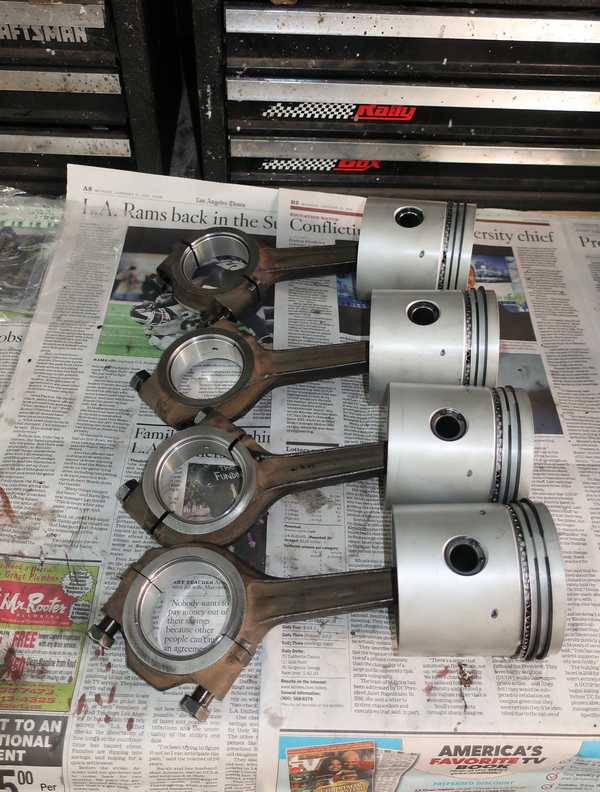
With a little encouragement and somewhat more oil, the outer two pistons slid out of their cylinders. The inner two were frozen solid.
![]()
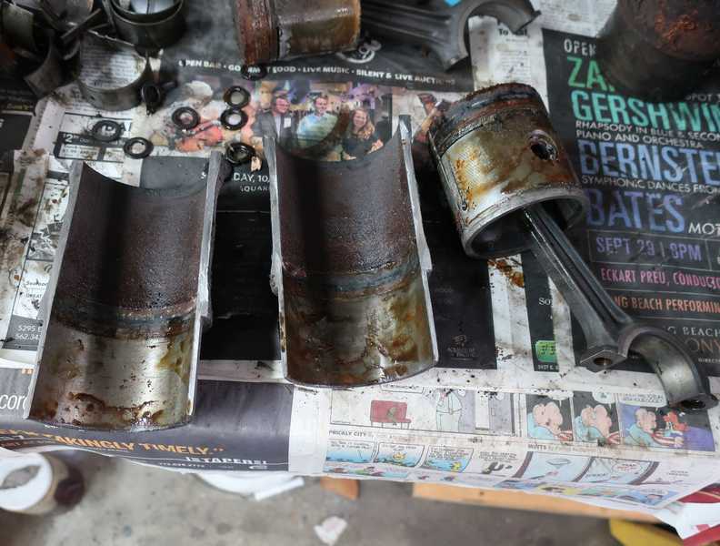
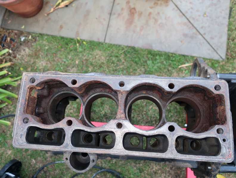
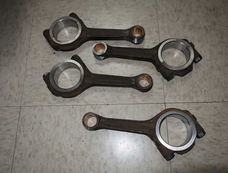
The cylinders were tight, but I was able to remove them with a hammer and aluminum drift. To remove the frozen pistons, I cut the cylinders lengthwise with an angle grinder and cutting wheel. The pistons and cylinders were trash, but I wanted to save the connecting rods.
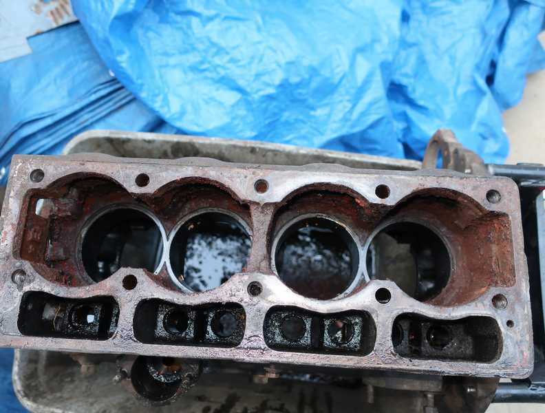
There was no sealer visible on the copper figure-eight gaskets or on the sealing surfaces of the block; a mild surprise. The sealing surfaces actually looked pretty good, better than those on my primary TR4A engine. At this point, the block needed a good cleaning and removal of loose rust from the coolant chambers.
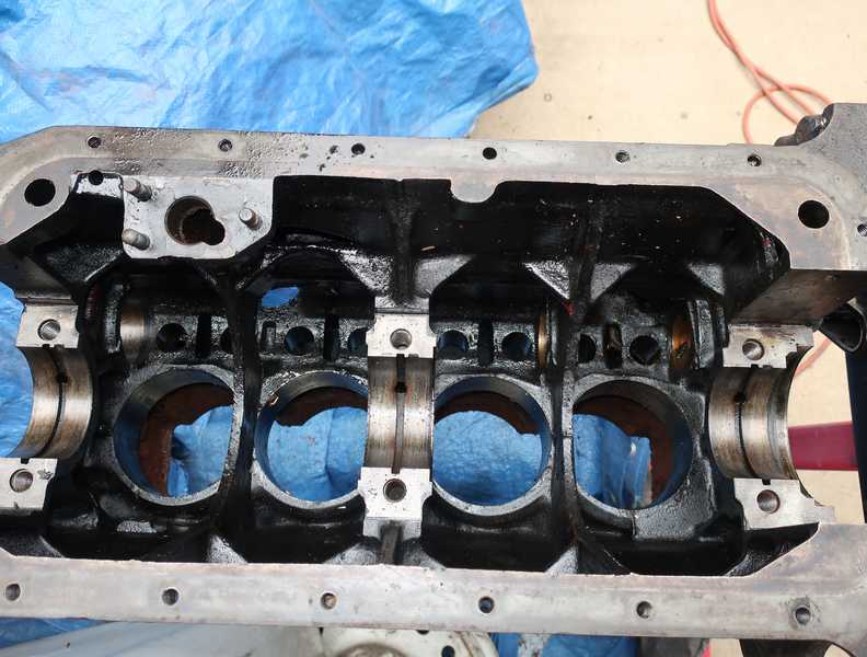
Once the engine was clean, I ran a bore gauge through the main-bearing bores and found them to be within spec. I also checked the big-end bores of the connecting rods, and they were OK too. I probably could have reused them as they were, but for $6 per rod, they were sent out to the machine shop and honed to perfection.
I measured only one cam bearing, just out of curiosity, as I planned to replace them anyway. That bearing had significant ovality, measuring 2-5 mils larger ID than the camshaft spec. All the cam bearings showed considerable wear.
To remove the bearings, I used the extractor that I made for the first engine. I used this tool for installation, as well.
Cleaning
No pictures of the cleaning process. It was straightforward, and it would probably just gross you out anyway. It's invariably a messy job.
The usual: I scrubbed the block well with solvent, inside and out, using a variety of bristle and wire brushes. That removed the oil and greasy black crud. I then washed it with my pressure washer, first a detergent wash and finally a high-pressure spray.
After cleaning the block, I dried it with compressed air. I was careful to blow out all the screw holes and oil passageways. Even areas that were especially cruddy, like the back side of the block and the tappet chambers, were cleaned of all crud and loose residue.
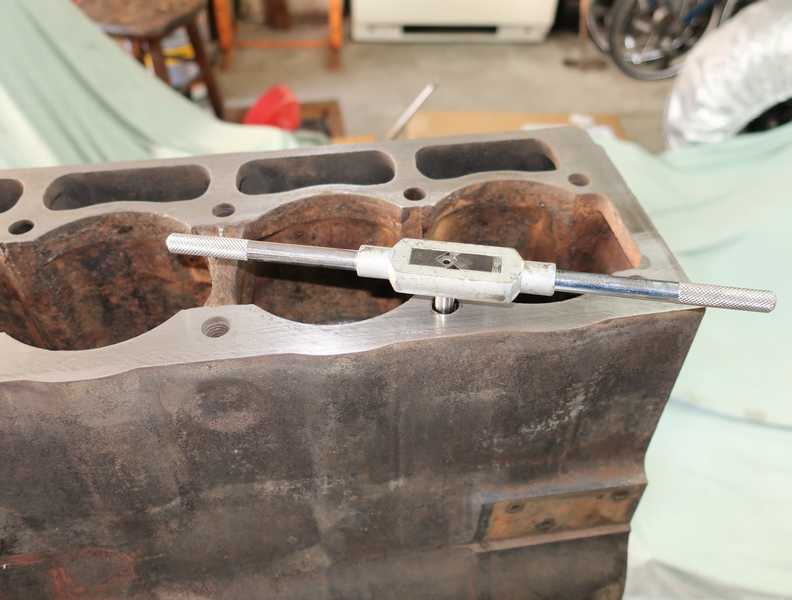
I cleaned much of the rust out of the coolant chambers with a variety of wire brushes mounted on an electric drill. I turned the block on its side, flushed the head-stud holes with carb cleaner, and blew them out with compressed air. Finally, I chased the threads with a long tap (four of them are deeply recessed) and oiled them to prevent rust.
I cleaned the oil passageways by first running pipe cleaners through them, to make sure they were clear and to get a sense of how cruddy they were. I then flushed them with lots of carb cleaner.
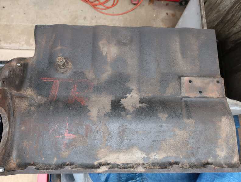
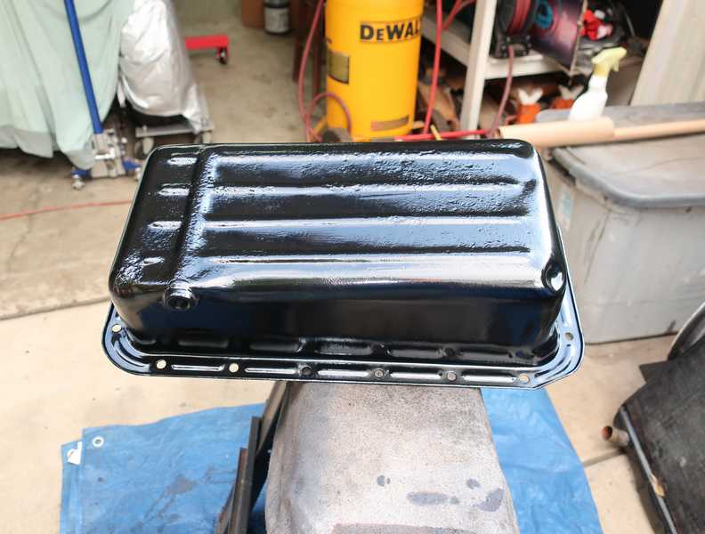
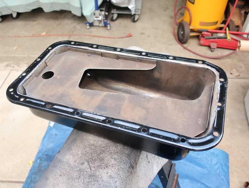
I cleaned the oil pan and painted it with the same high-temperature paint and primer I used for the engine. Although there was significant rust pitting on the underside, it was not close to penetration, so the pan was still usable.
Test Fitting the Cylinders
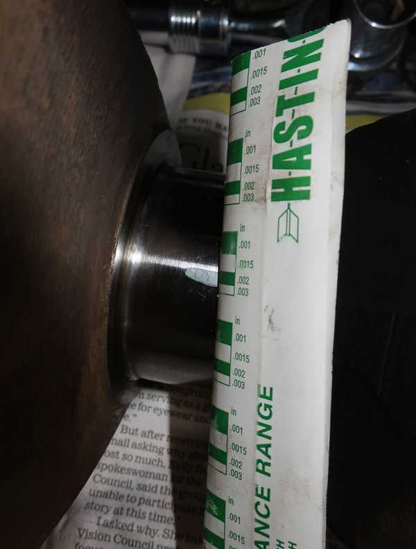
The tricky part in installing the cylinders is to set the top protrusion above the block surface, specified as 3-5 mils. That's a narrow range, and it is reportedly a critical dimension. Achieving it requires test fitting the cylinders and, if necessary, adjusting the gasket thickness.
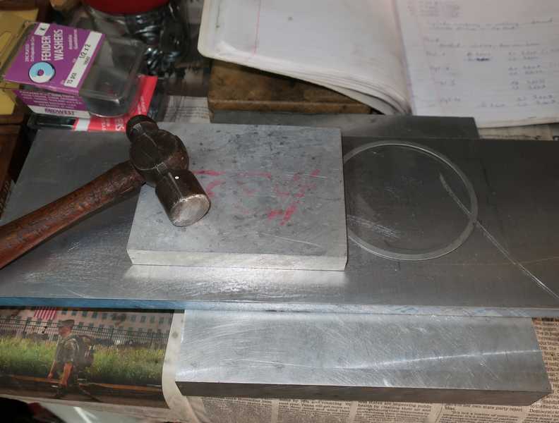
I smoothed off the top of the block by sanding it with 220 grit paper wrapped around a large aluminum block. When it was smooth, I checked the surface with a dial micrometer. Fortunately, it was quite flat--well within 1 mil over most of the surface.
I measured the depth from the surface of the block to the cylinder shelves with a depth micrometer and a machinist's parallel (since the micrometer would not reach all the way down to the shelf). I obtained 4.497-4.498 inches for all of them. I also measured the distance from the top of each cylinder to its mounting surface, obtaining 4.487 inches, plus or minus a few tenths of a mil, for all. The 15-mil steel gasket, which was supplied with the cylinders, should have provided 4-5 mils of cylinder protrusion, an ideal situation. (I also had several copper gaskets, which I prefer, but they were 20 mils thick. Sanding them down to ~15 mils is possible, but really not fun.)
With my first engine, I observed considerably more protrusion than I expected, based on the same measurements. I wrote this off to irregularity in the gaskets and surfaces, and with some finagling, got them all into spec. This time, however, I wanted it to work out better, so I did the following:
- I made sure that the gaskets were flat and burr-free. To remove the burrs, I rubbed the head of a ball-peen hammer around the edges of each gasket while it sat on a large aluminum block. Then, to flatten the gaskets, I hammered them between two thick aluminum blocks.
- I kept the gaskets and cylinder-mounting surfaces scrupulously clean, preventing bits of debris (for example, rust from the inside of the block) from falling onto them.
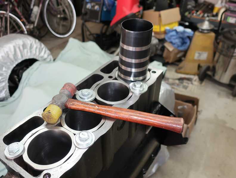
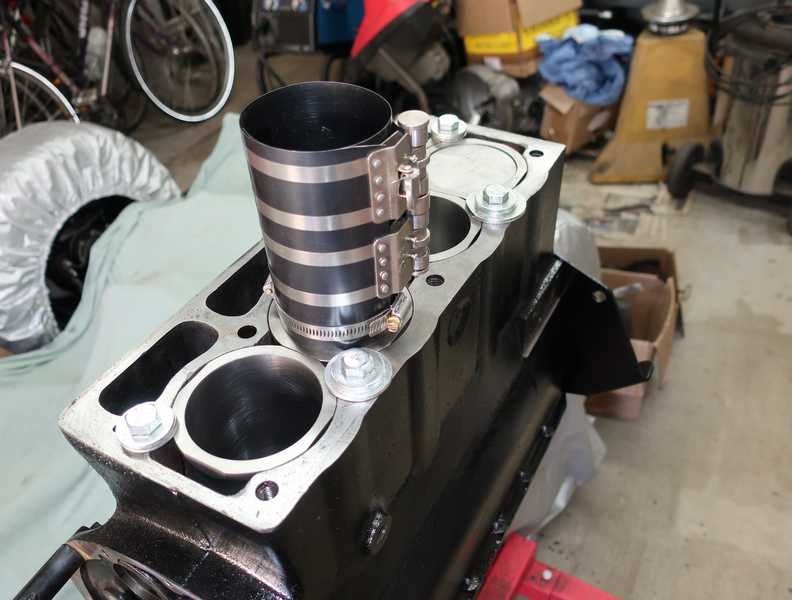
- After inserting each cylinder, I tapped it into place firmly with a hammer and wood block. That guaranteed that the gasket was fully flattened and seated.
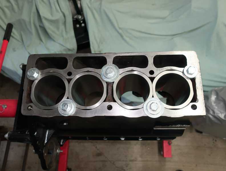
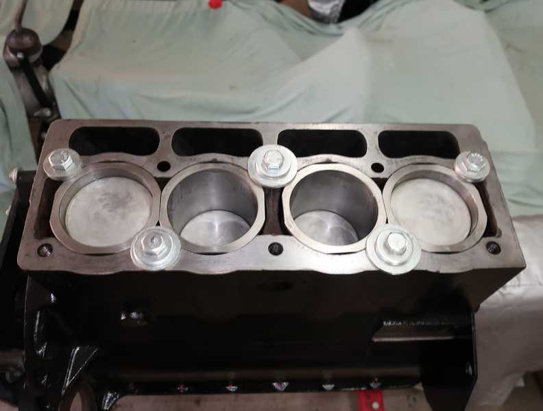
- Finally, I installed bolts and large washers in the head-stud holes to compress the gaskets and hold the cylinders in place. I then measured the protrusions.
Below are some pictures of the process.
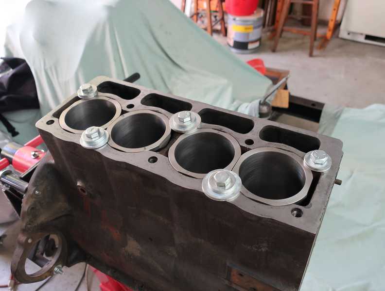
I measured the cylinder protrusion with a depth micrometer, which is more accurate than the usual method involving a metal ruler and a feeler gauge. It does require a little care in determining the depth, as the "feel" changes only slightly when the rod touches the block. When installed, the gaskets have sealer on them. Previously, I found that the sealer did not measurably affect the protrusions, as almost all of it was squeezed out when the cylinder was installed. The remaining sealer simply filled irregularities.
The effort paid off! On my first try, I measured 4-5 mils protrusion for all of the cylinders, except for one small area that was 2.5 mils, just a little outside the 3-5 mil spec. I switched that cylinder with one having a larger dimension between the top and mounting surface, and that raised it to just over 3 mils. I rechecked all the other cylinder protrusions, and they remained at 4-5 mils.
I marked the cylinders' and gaskets' locations and orientations before removing them.
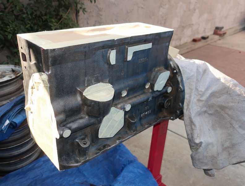
Painting the Block
I went over the block with a wire wheel in my angle grinder and used a pin scaler for places that the wire wheel couldn't reach. I then cleaned it with grease and wax remover and finally masked it.
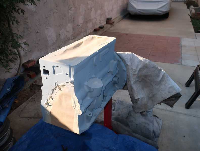
I used Duplicolor rattle-can engine paints for both the primer and finish coats. First, a couple coats of primer.
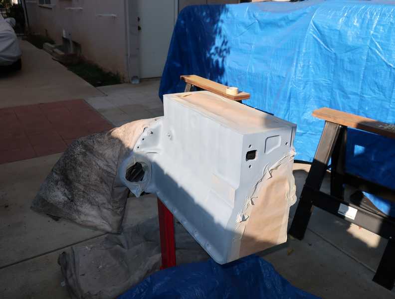
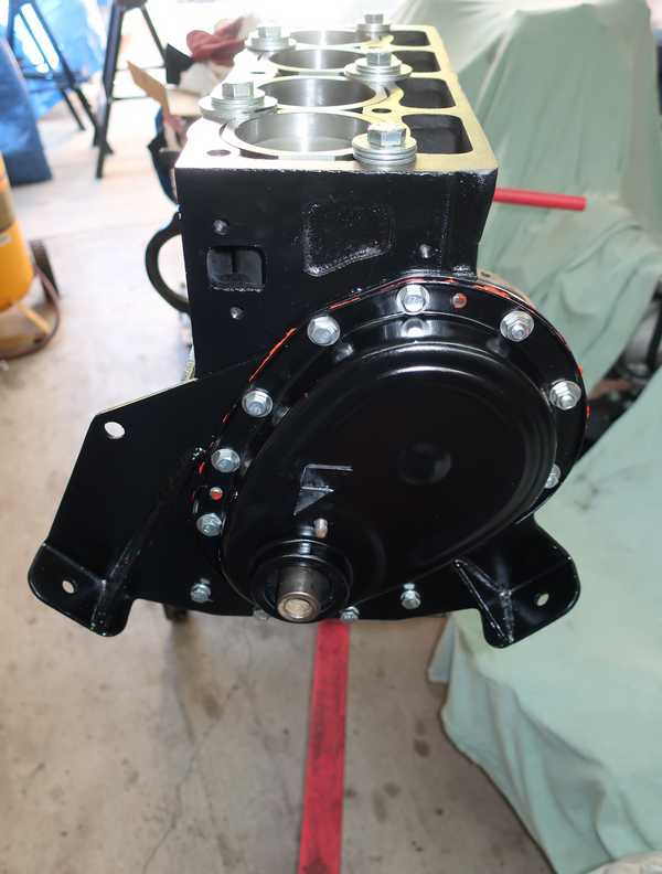
Finally, a couple coats of engine paint. The finished block is shown below.
Internal and External Parts
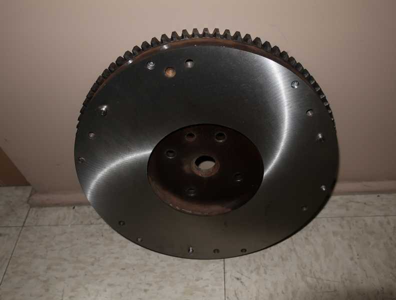
Flywheel
As I noted earlier, the engine's TR4A flywheel needed a new ring gear. Fortunately, a ring gear is not expensive, and installing it is straightforward. With most cars, you just heat the gear with a torch to expand it, slip it on, and let it contract into place. The TR4A ring gear, however, is bolted onto the flywheel. It's still an interference fit, but not very tight; you can use the mounting bolts to pull it into place, no heating needed.
Instead of the tabbed locking plates, which are ineffective or worse, I used 1 1/4-inch, grade-5 bolts with permanent (red) loctite, correctly applied per the manufacturer's specifications, and correct torque. No spring or flat washers. I don't understand why lock plates were used in the first place; this is not an application where properly torqued bolts are likely to loosen.
I had the flywheel resurfaced and balanced. In the second picture, you can see holes on the edge where metal was removed for balancing.
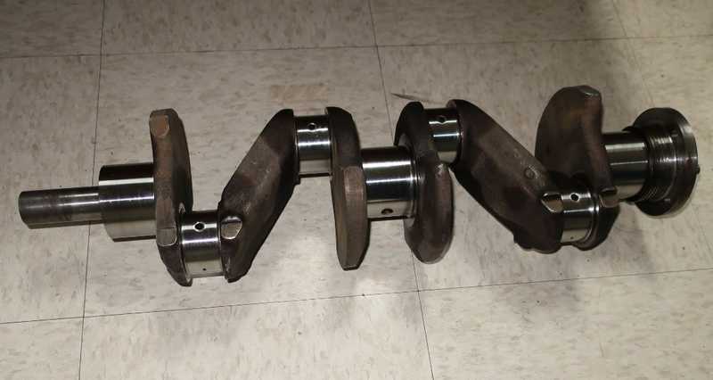
Crankshaft and Connecting Rods
The crank was ground 0.010" undersize on both the main and rod journals. I had the big ends of the connecting rods checked and resized, and had the shop install and size the wrist-pin bushings. Finally, everything was balanced, so it should run nice and smooth.
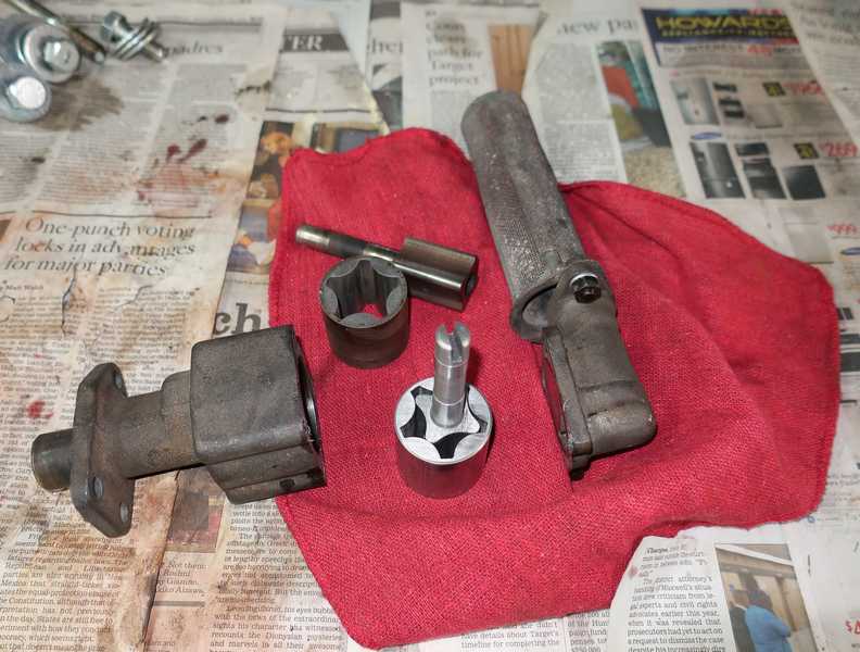
Oil Pump
The oil pump was partially plugged with sludge. Petroleum solvents didn't touch the disgusting goo, but acetone dissolved it easily.
The pump is a simple device, easy to check with just a feeler gauge. The existing innards were within spec, but just barely, so I chose to install new ones. It's a simple and inexpensive restoration, just thirty bucks, two new parts, and four bolts.
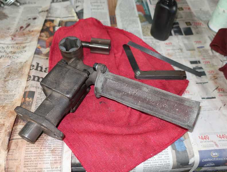
It's dangerous to assume that new parts are made right, so I checked their clearances, as I did the old ones. All was well.
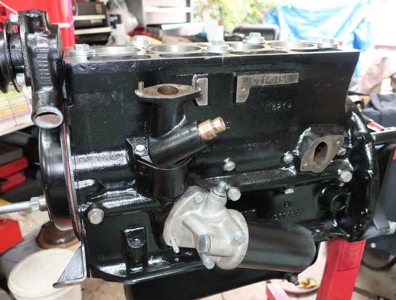
Here is the installed oil pump. For some reason, the gasket set included an oil-pump gasket. I installed it, but it seemed pretty silly--very little (if any) oil could leak through the wide, closely fitting joint between the pump and block, certainly not enough to affect oil pressure. And what if a drop or two got past it? The oil would just drip back into the sump.
Originally, the oil pump was mounted with studs, probably because the block is tapped UNC, but the studs allow UNF nuts to be used. I used UNC bolts; the difference is minor, and I used high-strength, high-temperature thread locker to make sure that they stay in place. They are not, in any case, likely to loosen.
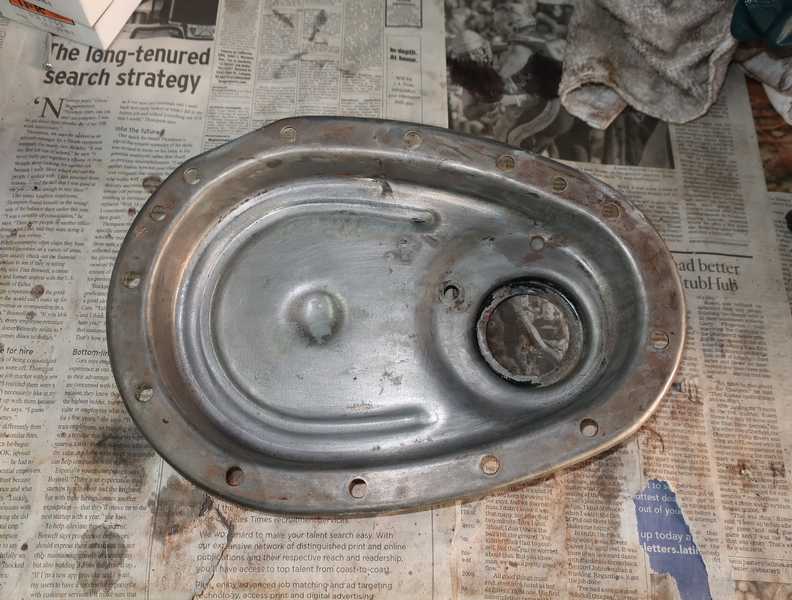
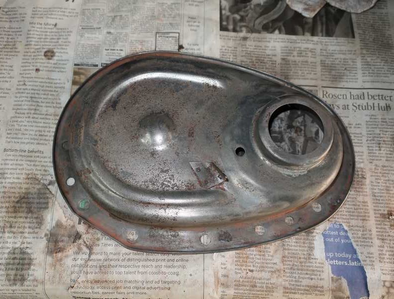
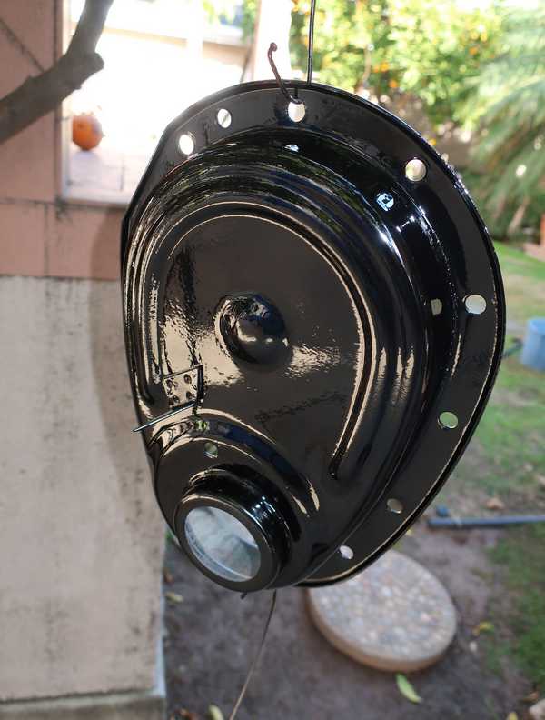
Timing Cover
Below, the timing cover has been degreased and cleaned up somewhat. I used chemical paint stripper to remove paint on both the outside and the inside. The inside of the timing cover had been painted, a stupid thing to do. It's not going to rust, as it is continuously covered with oil, and paint could flake off and get into the oil. The paint remover didn't touch the red-lead primer on the outside, so I had do something different to remove it.
I sanded off the remaining primer (while wearing a mask, of course, to avoid breathing the lead-containing dust) and removed the remaining rust with phosphoric acid.
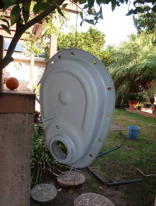
I primed and painted the outside of the cover with engine paints.
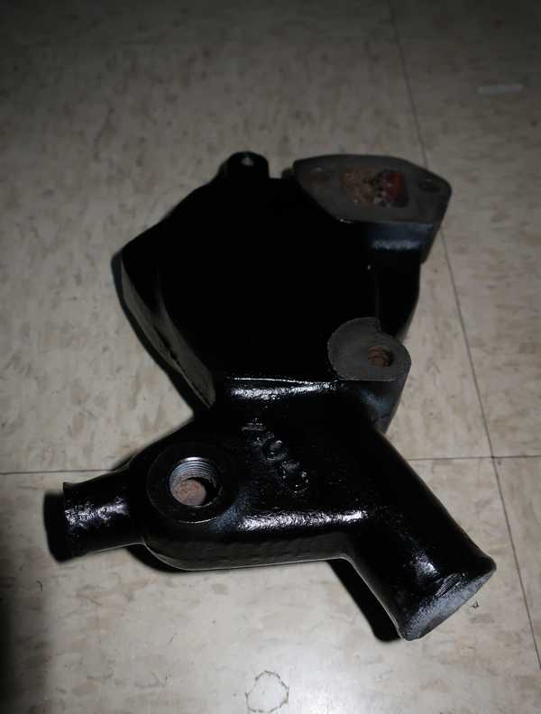
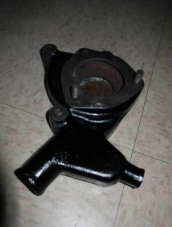
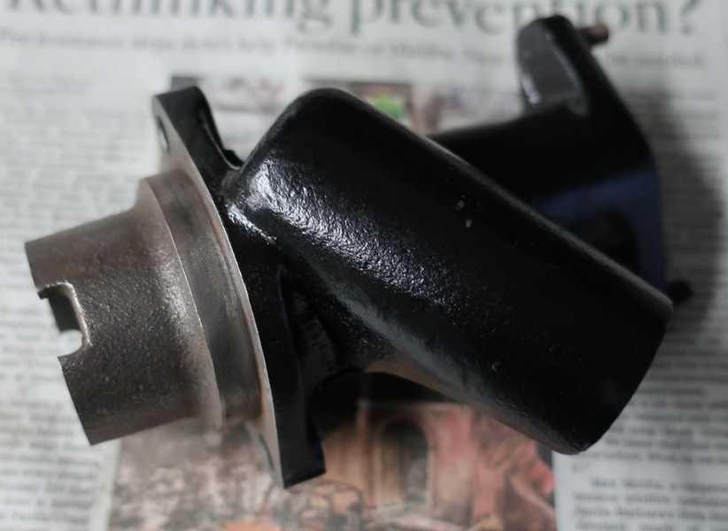
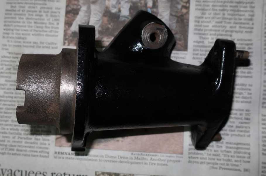
Water Pump
I similarly cleaned the water-pump body and left it in a phosphoric-acid bath to remove both internal and external rust. I didn't get every last speck of internal rust off, but that shouldn't be a problem; this is, after all, the cooling system we're talkin' about, where a certain amount of rust is inevitable. The phosphoric acid created a nice iron phosphate coating, which was a good substrate for paint.
I washed the part well in detergent, rinsed and dried it, and finally masked, primed, and painted it. Engine paints, as usual.
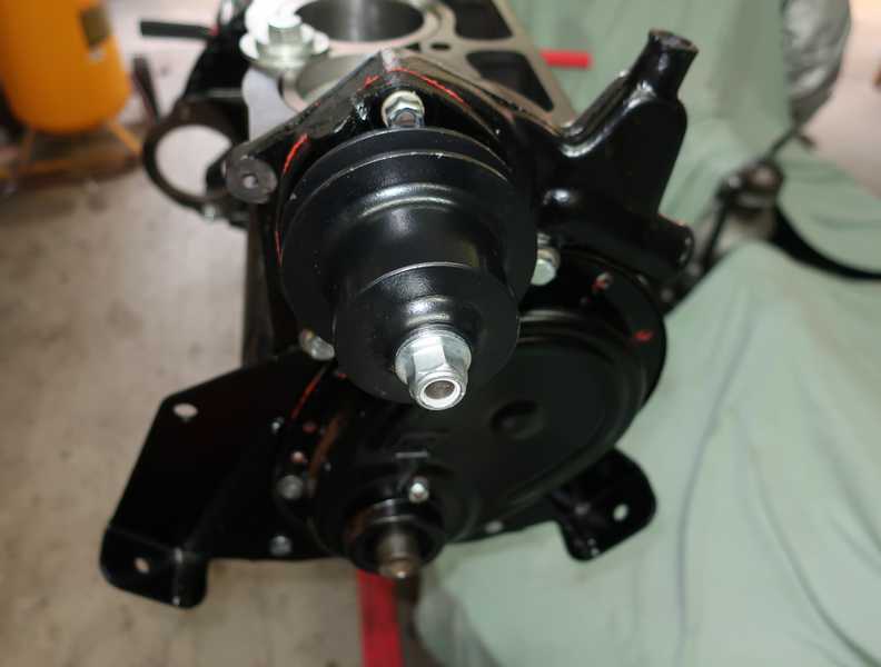
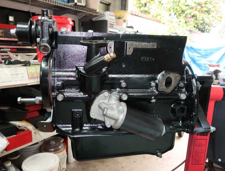
I bought a new four-vane water pump and pulley; it probably moves a little less water than the five-vane one I used on the original engine, but it avoided the nightmare installation problems of the five-vane. I quote a common aerospace-industry axiom: better is the enemy of good enough. Below, the pump and body are installed on the engine.
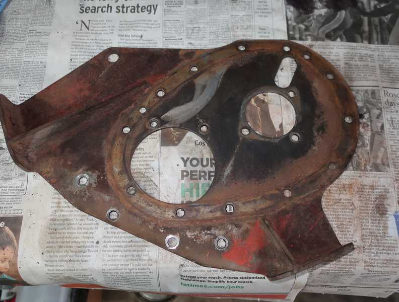
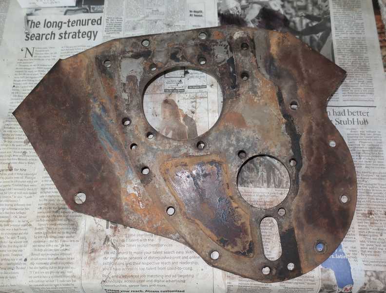
Front Plate
The front plate was pretty ugly but had no problems that cleaning and paint couldn't fix. The timing-chain tensioner had worn a groove in the plate, probably caused by a loose tensioner and excessive chain wear. The fix is to fill the groove by welding, then machine it flat. I decided not to do that, however, because it's a shallow defect, which shouldn't cause any problems as long as the chain and tensioner are set up right.
The chain tensioner is just a thin wand of spring steel, which doesn't inspire confidence. Furthermore I have learned of two problems with the ones currently available: first, many are not properly tempered, and they bend easily; second, they often have rough edges, which dig into the plate. Conversely, the chains sometimes have rough edges, which dig into the tensioner.The solution to the first problem is to throw away the part and buy something that's right. For the second, the solution is simply to sand off the rough edges.
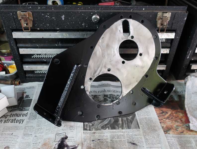
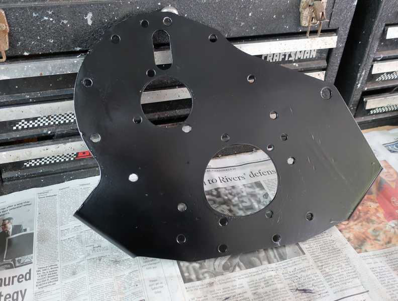
I cleaned the plate with a polycarbide disk in an angle grinder, a succession of wire brushes, and finally hand sanding. I masked the area that eventually would be inside the timing cover; some people just paint it along with the rest, but I was concerned that paint might come loose and get into the oil. I primed and painted it with my usual engine paint.
Distributor Pedestal
I bought a replacement for the cracked distributor pedestal, cleaned and wire-brushed it, then masked, primed, and painted it.
The pedestal included a tachometer drive gear, which I removed for cleaning. That gear is invariably frozen in the pedestal. I removed it by soaking the gear for a day or two in automatic transmission fluid. I didn't completely immerse it, just dripped some into the inside and into the setscrew hole. I've removed two of these gears this way.
Before installing the pedestal on the engine, I reinserted the drive-shaft bushing, as I had removed it to prevent damage during cleaning. It's a fairly tight press fit into the block. I then checked the distributor drive's end float. Using the procedure in the shop manual, I measured 5 mils of float, an ideal value, so no adjustment was needed. This is an important specification, as the channel into which the shaft fits is pressurized with oil. If the gap is too great, it can affect the oil pressure.
Installing the distributor drive is a little tricky, as it has to fit into a drive gear on the camshaft, the slot in the oil pump, and be in the right position for the distributor. You might think that the latter requirement would not be important, as you could rotate the distributor so it is properly timed, no matter how it sits on the pedestal. However, there isn't much room for that kind of adjustment, so it's best just to follow the manual and get it right.
The manual describes a rather odd procedure for setting the distributor-gear end float. It's important to take that seriously, as the shaft is pressurized with oil (it goes through the main oil gallery), and excessive end float could reduce the oil pressure.
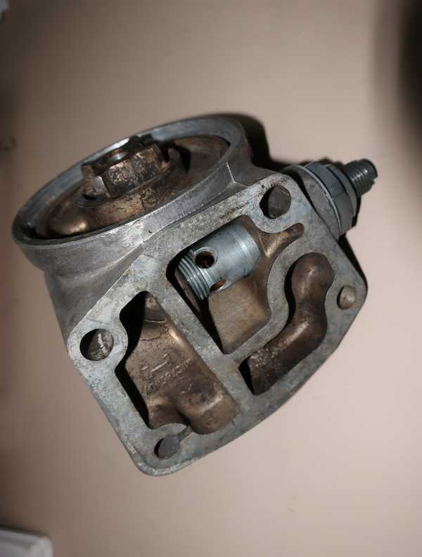
Oil Filter
I restored the oil-filter head by cleaning the body and replating the pressure-relief and bypass hardware. The pressure relief originally used a lead ring under the adjuster locknut; a copper washer will not work there (think about it!), so I put some nonhardening sealer on the threads. That should allow some degree of adjustment without leakage.
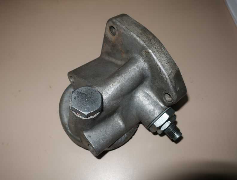
I also replated the original bolts and stud, as the sizes are a little odd, and I didn't have new ones that would fit.
For now, I installed the original type of canister filter, but a spin-on filter conversion using the existing head is also available.
You can find more information on the TR oil filter here.
Engine Assembly
Camshaft Bearings
Installing camshaft bearings is a colossal bitch. They can be inserted a couple different ways, only one of which is right, so it is easy to install them wrong. If they are not installed correctly, oil passages to the bearings will be blocked. They fit tightly and require a lot of force for installation, so they are easy to damage. The bearings are not keyed, so there is no easy way to ensure that the oil holes line up. Then, as I discovered, when the oil holes are right, the setscrew holes of our sloppily designed, modern repro bearings don't line up correctly with their holes in the block.
The installation of camshaft bearings is described well in the page on the original engine; no need to repeat that here. One point worth making is the importance of checking that all the oil passageways are clean and open. If the block's oil pathways are not clean, any remaining crud has nowhere to go but into the bearing.
My trusty camshaft-bearing tool was used to install the bearings. I'm getting better at this; I had to remove a bearing and reinsert it only once. I test-fit the camshaft; it slid into place nicely and turned smoothly.
Cylinders
I made sure that the metal cylinder gaskets and flange surfaces were clean and oil free, coated them with a goodly amount of Permatex no. 3 sealer, and installed the cylinders. To make sure that the cylinders were fully seated, I tapped them into place with a hammer and wood block. I measured the protrusions and compared them to my earlier measurements, when I test fit the cylinders. If the cylinders were too high, a little more work with the hammer and block got them seated properly. I reinstalled the bolts and large washers that prevented the cylinders from moving.
Crankshaft Installation
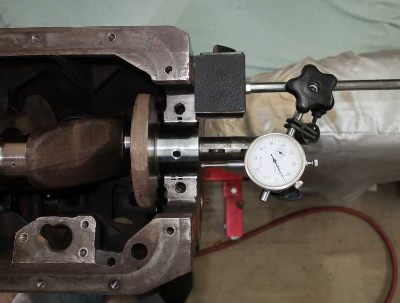
Before installing the crank, I checked the main and connecting-rod bearing clearances with plastigage; all were around 2 mils, a good number. I also installed the center bearing cap, plus the thrust bearings, and measured the end float, which was a perfect 5 mils.
I test-fit the connecting rods similarly and checked their clearances with plastigage.
I installed the camshaft and greased its lobes with assembly lube. It's easier to do that before the crank is installed.
Also, before the crank is installed, the rear scroll seal must be installed and adjusted. That requires a special, precisely machined mandrel that fits into the rear main-bearing bore. The halves of the seal are then located so they contact the protruding mandrel. As long as the mandrel is used, aligning the seal is straightforward. The only tricky part is to make sure that the surfaces of the bearing caps, both front and rear, are flush with the block surfaces. That's necessary to obtain good gasket sealing in the front and scroll-seal effectiveness in the rear.
The halves are a matched set and are marked as such; sets must not be mixed. There is no gasket between the seal and the block, but a little sealer on the flanges is probably prudent.
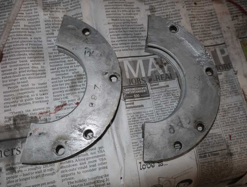
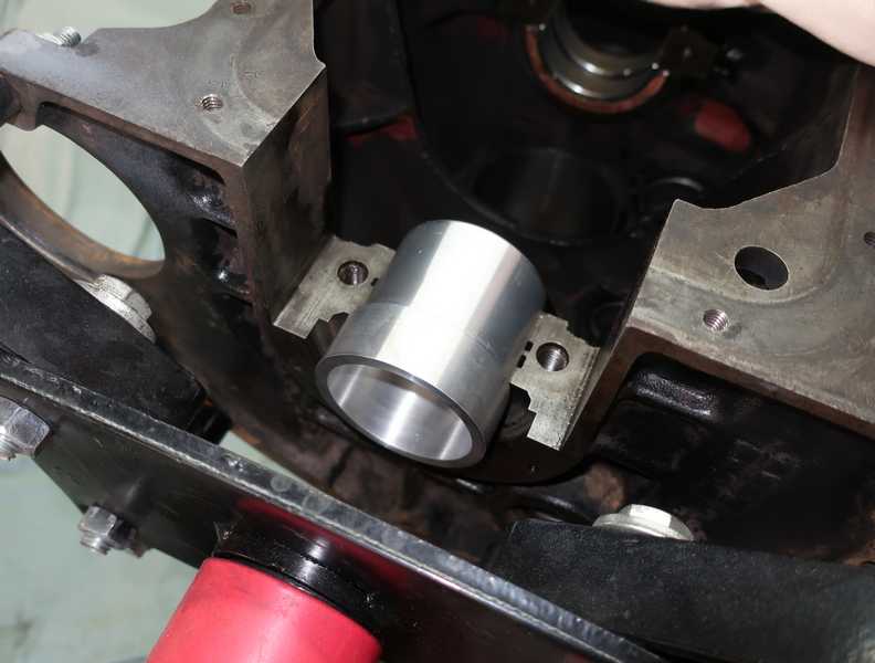
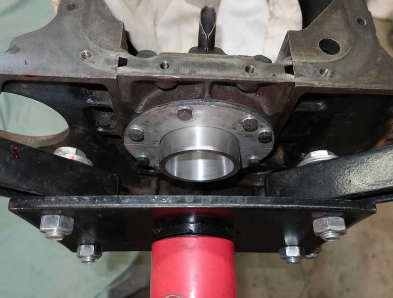
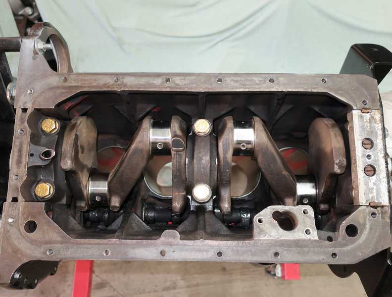
Below are the installed crank, with new bolts for the main-bearing caps, and the scroll seal. The square slots in the sides of the rear main-bearing cap hold a felt seal, which I hadn't yet inserted.
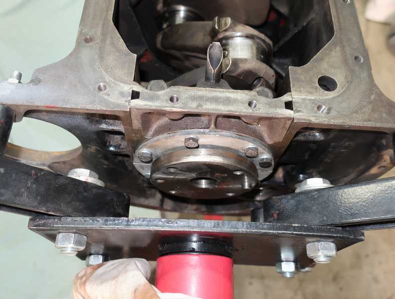
The felt seal is cut into one-inch pieces, which are coated with sealer and rammed into the gap. In the picture below, a little sealer remains on the block. It was removed with lacquer thinner.
Pistons
I ended up with County pistons and liners and Hastings rings. I like the Hastings rings, if only because the ends of the oil ring can't slip and overlap, like the Grant rings on my first engine. I checked the ring end gaps in the usual manner, as well as the groove clearance. I was careful to locate and orient the rings correctly.
The piston-ring compressor shown below, although hawked damn near everywhere, is a piece of unmitigated crap! It may have been OK for the upper rings, but, because I couldn't get it tight enough against the block, the very narrow oil-ring retainers repeatedly got stuck at the block surface. I finally made it work by turning it over and using a large hose clamp to hold the end shut. It still took most of the afternoon to install the pistons.
I wrapped the big ends of the rods in masking tape, so they wouldn't scratch the cylinders.
And, here they are, finally installed in the block. The connecting-rod stretch bolts, of course, are new. They are installed with the specified torque and a little high-temperature loctite.
Camshaft Timing
The procedure for timing a TR engine is described in my first engine page; I won't repeat it here.
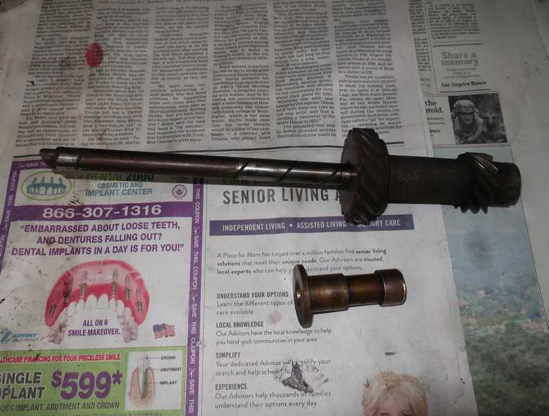
I attached a degree wheel to the camshaft. It's used, along with the dial indicator, to find the camshaft position when the no. 1 piston is at TDC on the exhaust stroke. To find TDC precisely, I used a degree wheel on the crank, as well.
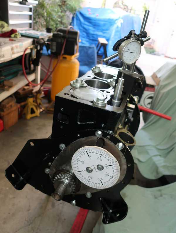
Here's the new camshaft gear. The original attachment bolts had about a quarter inch of unthreaded shank, which helped to locate the gear precisely. I could not find a high-strength bolt with a similar shank, but fully threaded, grade-8 bolts fit the holes with only a few mils of clearance. That resulted in less than 0.2 degrees of position uncertainty, easily good enough. I used Nord-Lock washers instead of the original, hopeless tab washers. I expected them to be far superior; they could hardly have been worse.
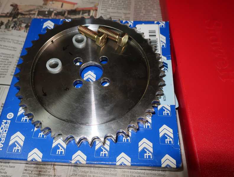
By the way, the cam-gear bolts must be grade 5 or 8; the specified torque, 25 lb. ft., is much too great for grade 2 or 3 bolts.
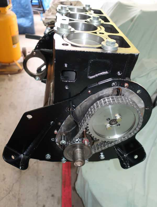
Following my established procedure, I determined the camshaft and crank positions for correct valve timing, installed the gears and chain, and torqued the camshaft gear's bolts. Once it was all together, I rechecked the timing by making sure that the camshaft lobes raised the substitute tappet the same amount on equal sides of TDC. That test showed that the timing was right on.
I installed the cover temporarily to compress the sealer, which was applied to only one side of the gasket. For now, it will not be sealed on both surfaces, as I may want to remove the cover occasionally to oil the gears and chain for preservation. Same story for the oil pan.
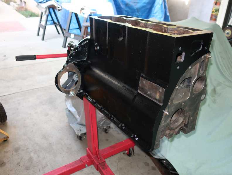
Final Items
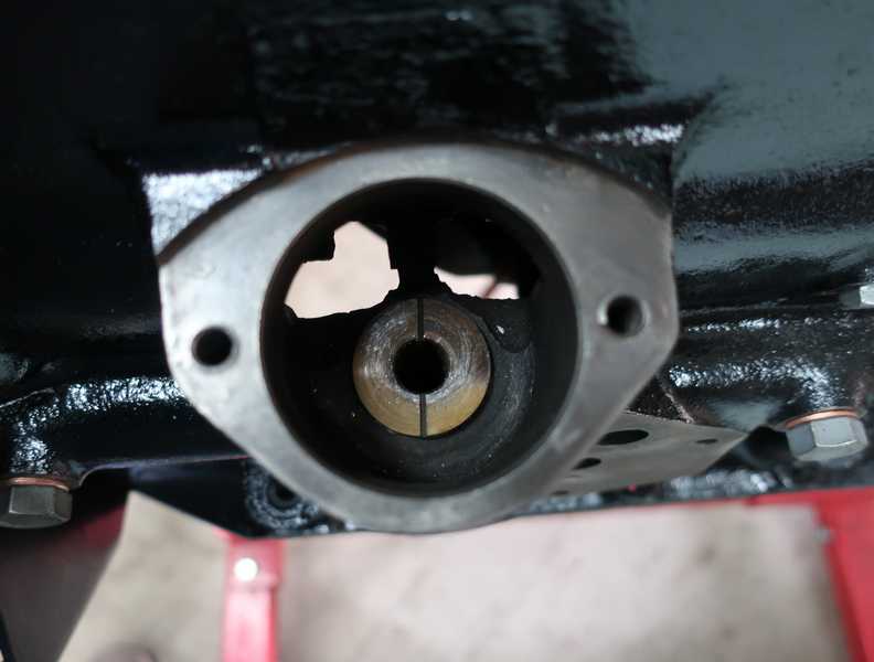
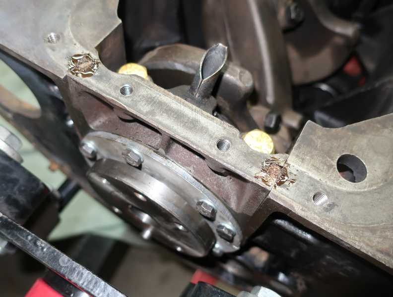
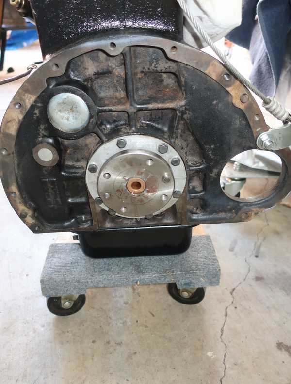
With all that stuff in place, it was time to take the engine off the stand and finish the rear. First, I installed the plug over the rear opening for the camshaft. Even without sealer, it fits fairly tightly and the pressure behind it is not great, so it probably wouldn't leak. Even so, I used a minuscule amount of sealer, just enough to fill in the corners of the recess where the plug sits. To tighten it in its hole, I dimpled the center with a hammer and drift. That circle just below the camshaft plug is an aluminum plug that seals the end of the oil gallery. It is a common leak point, as it has full oil pressure behind it. Unfortunately, there is no way to leak-test it; you just have to examine it carefully and hope you're right.
I also installed a new pilot bearing, a sintered bronze bearing, which I had left soaking in oil a few days.
Next was the flywheel. It requires special "locking" bolts, which don't lock in any way I can see. The heads are a size larger than usual for 3/8-inch bolts, but that's the only visible difference between them and ordinary UNF fasteners. I used thread locker on them and torqued them to the requisite 46 lb ft. The aluminum block, if you haven't figured it out, is an impromptu crank locker. It worked just fine, but in retrospect, it's probably not the best way to lock the crank. Both of my TR engines arrived with missing ring-gear teeth, so I could be convinced that they are a little fragile. Better to use something that spreads the force over a number of teeth.
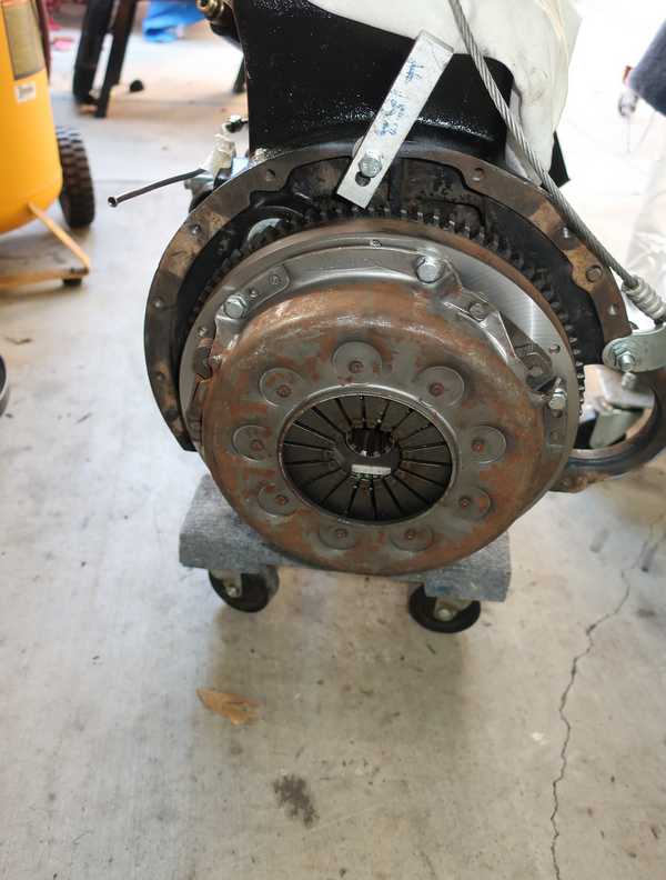
I installed the original clutch from my TR4A on the flywheel. In spite of the small amount of visible rust, it was still in very nice condition; the wear on the disk and spring fingers was imperceptible.