Alternator Conversion
Steve
Maas
Long Beach, California, USA
November, 2007
 As
of the beginning of this project, my 1960 Bugeye Sprite still had its original generator. Since I had added
an ammeter, I'd been able to observe the generator's clear inability to keep up
with the electrical load. The generator would probably be OK if the Sprite had
only its original equipment, but mine had a cooling fan, an electronic
ignition, and an electric fuel pump.
Together these required about 12 amps; at idle, the generator could put out only
a few amps, so the battery had to provide 8-10 amps of current. Above 1500 RPM, the generator
could meet the load,
as long as the headlights weren't on. The halogen lights, however, drew a bit
more current than the original non-halogen incandescents; when they were on, the load on the
battery, even at speed, was close to 20 amps. That was just not acceptable. I
recognized that I needed more
current, or someday I would be stuck with a dead battery. Thus, the decision to
replace the old DC generator with a modern alternator.
As
of the beginning of this project, my 1960 Bugeye Sprite still had its original generator. Since I had added
an ammeter, I'd been able to observe the generator's clear inability to keep up
with the electrical load. The generator would probably be OK if the Sprite had
only its original equipment, but mine had a cooling fan, an electronic
ignition, and an electric fuel pump.
Together these required about 12 amps; at idle, the generator could put out only
a few amps, so the battery had to provide 8-10 amps of current. Above 1500 RPM, the generator
could meet the load,
as long as the headlights weren't on. The halogen lights, however, drew a bit
more current than the original non-halogen incandescents; when they were on, the load on the
battery, even at speed, was close to 20 amps. That was just not acceptable. I
recognized that I needed more
current, or someday I would be stuck with a dead battery. Thus, the decision to
replace the old DC generator with a modern alternator.
To see a larger version of any of the pictures, click on its thumbnail.
Alternator Conversions
The greatest dilemma in converting a Sprite to an alternator is the tachometer. Since the mechanical tach is driven from the generator, the first part of an alternator conversion must be the installation of a new tach. The conventional solution is to install an electronic tach from a later Spridget. My solution was to create an electronic tach that looks just like the mechanical one. Click here for the description of my tachometer (a PDF file).
A second consideration is that modern alternators are all negative-ground (or negative-earth, if you prefer the British terminology). Thus, any positive-ground car must be converted to negative-ground before an alternator can be installed. Unless positive-ground equipment has been added, the change is trivial. A quick internet search will provide lots of information on positive-to-negative ground conversions. A final, very minor, consideration applies to early Bugeyes that have the ignition coil mounted on the generator. The coil obviously will have to be relocated.
There is plenty of information on the net regarding alternator conversions for British cars. It's a common upgrade. I found the information at Muenchausen's Garage to be especially useful. In particular, the recommendation of the Bosch 13107 alternator, designed for 1978-80 Ford Fiestas, was spot on. This is a 55 amp alternator, which should provide all the current anyone with a Bugeye Sprite could wish for; is inexpensive; and fits the Sprite almost perfectly. This is the unit I used.
The Alternator
I purchased a rebuilt Bosch 13107 alternator from an online supplier. It is available from many sources, perhaps even your local auto-parts store. The alternator is a replacement for the one in a 1978-80 Ford Fiesta, so presumably any unit fitting that car will do. Some Fiestas had separate voltage regulators; be sure you get an alternator that has a built-in regulator. Electronically, the unit is fairly simple, and in any case, it is well described in Muenchausen. Since the alternator has a built-in voltage regulator, the only connections are to the electrical system and the "ignition" idiot light, which is really a charge-indication light. The old mechanical regulator is no longer needed. The alternator's voltage regulator adjusts the system to about 14V; the Sprite's original mechanical regulator centered the voltage around 13V, which is probably too low for good battery life. This modest increase in system voltage should not be a problem for any of a Sprite's electrical equipment, new or original.
One thing to watch out for: many replacement alternators don't come with a fan and pulley. This is no problem if you are replacing an identical alternator, but obviously, in this case, you need an alternator that includes these parts. Similarly, you may have to "eat" a core charge. Just part of the costs of having fun...!
Mechanical Installation
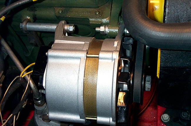
I was concerned that the distance from the mounting flange to the pulley might not be the same as with the generator, causing some belt-alignment problems, but it turned out to be exactly the same. The alternator is considerably shorter than the generator, so its mounting tabs are almost exactly two inches closer together. To accommodate this difference, I used a long bolt for the rear mount (a 3 1/2-inch long, 5/16-inch diameter bolt) and a 2-inch sleeve. For the sleeve, I bought a 3-inch long piece of 1/4" steel pipe and cut it to size with a hacksaw. (1/4-inch is a nominal size; the outer diameter is actually about a half inch.) I then finished off the ends in my lathe. With care, it could be done with a hacksaw and file.
The sleeve is a little tricky, as its length must be precise. There is some room for adjusting the rear generator-mounting bracket to make everything fit, but still the tolerance in the sleeve's length is only about 1/16 inch. Of course, if it's too short, it can be shimmed with washers, but I like to avoid such clumsy expedients. Getting it right is important, as any remaining stress on the alternator's mounting ears could lead to their cracking.

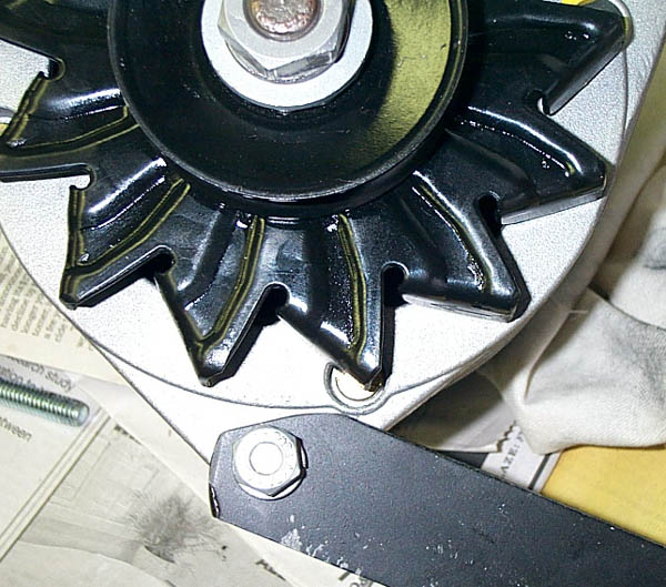
Some modifications were required to prevent the alternator's fan from hitting the lower mounting bracket,. This involved some cutting and filing to make the bracket a little narrower where it bolted to the alternator. I had to trim it a bit more than the picture, above, shows. Lengthening the slot in the bracket by about a half inch would make fan-belt removal a little easier, but that is not absolutely necessary.
Surprisingly, the existing fan belt fit just fine. There is adequate room to move the alternator for tightening the fan belt, and the access to the oil filter and starter are much improved.
Electrical Installation
It is important to disconnect the battery before working on the electrical system. If this is not done, the slightest short circuit will cause dramatic and scary electrical fireworks, resulting in serious damage. There is enough current available from a car battery to melt almost anything, and molten metal is more than a little dangerous.
The alternator has two 3/8" spade lugs marked "B+." Either of these is connected to the car's electrical system through a length of 10-gauge stranded wire. The old, mechanical regulator is no longer needed. The connections to the electrical system are as follows:
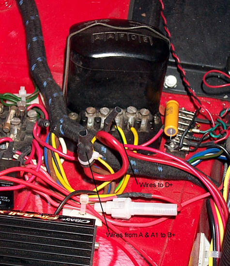
- The wires from the A and A1 terminals of the mechanical regulator are tied together and connected to the wire from the B+ terminal of the alternator.
- The wire to the F terminal of the regulator is disconnected and taped.
- The wire from the ignition indicator light to the D terminal of the regulator should go to the D+ terminal of the alternator; the other wire to the regulator's D terminal, which went to the generator's output, can be taped and left open.
- Any wires that went to the regulator's E terminal are grounded to the chassis at any convenient point.
Since the alternator has its own voltage regulator (a solid-state one, much better than the old mechanical type), the original voltage regulator is no longer needed.
The unused terminals on the alternator should be covered with some kind of insulation. A good method is to use a piece of shrink-wrap tubing. All unused wires dangling from the harness are tied out of the way, so their terminals do not accidentally touch something and create a short circuit.
A connection diagram is shown below:
Muenchausen recommends using two wires from the B+ to the car's electrical system. I suppose this can't hurt. However, in such arrangements, the resistance of one of the B+ connections is invariably a few hundredths of an ohm higher than the other. Because the resistances of the current paths are so low, even a small resistance increase in one path causes the other path to carry most of the current. It's very difficult to get two paths to have exactly the same resistance, so using two wires never really doubles the current-carrying ability. In the end, I chose to use both spade connections on the alternator but a single B+ lead. 10-gauge wire is easily good for 30A, and I can't see the current, in this car, ever being any greater than that. The pictures below show the connection to the alternator and near the regulator; I plan to remove the old regulator, although it still appears in the picture.
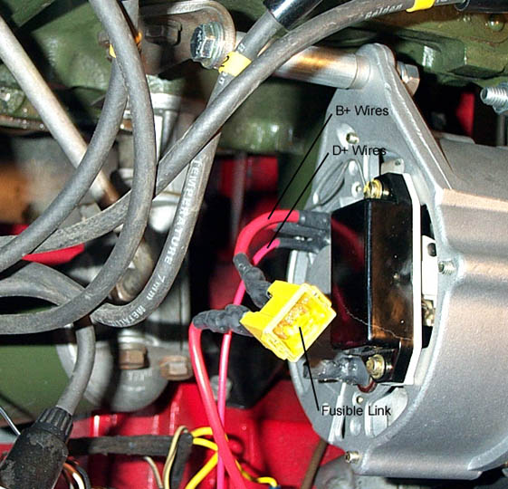
I added a 60A "fusible link" in series with the B+ lead. (I don't know why the manufacturer calls it that; it's really just a fuse.) The concern is not for the wiring or protecting the alternator; after all, if the current in this lead hits 60A, it's a sure thing that the alternator has died. The main problem concerns the alternator diodes; if they blow, they usually become short circuits. Then, the alternator could draw quite a bit of current, melting internal parts and possibly starting a fire. A similar problem could arise if the regulator electronics died; the defective part might also draw enough current to start a fire.
Results
The alternator requires no adjustments or other "tweaking." Just start the car and it works. On first start-up, the difference between the alternator and generator was immediately obvious. The system voltage was steady at 14V (it had been 12V with the generator), and instead of nearly 10A drain at idle, there were a few amps of charge current. The higher voltage should not be a problem for any stock electrical components, and certainly won't be a problem for modern additions, such as my electronic ignition and fuel pump. The only potential problem might be the fuel gauge; it is designed to be insensitive to system-voltage variations, but might not handle variations this great.
A more interesting issue is the alternator's mechanical load on the engine. Since the alternator produces considerably more power than the generator, one might expect it to load the engine more, thus using more horsepower that would otherwise be available to the wheels. Indeed, at full output, the alternator produces 770 watts (assuming 14V and 55A), just a little over one horsepower (1 HP = 746 W); accounting for its less-than-perfect efficiency, one would expect the maximum engine load to be something like 1.5 HP. However, there are other considerations: first, the alternator, being more modern, is probably more efficient than the generator; second, the alternator's electronic regulator probably makes better use of the available power, thus indirectly improving the efficiency; and, finally, the alternator will rarely, if ever, be fully loaded. The alternator load does decrease the idle speed about 100-200 RPM, but a grain of gnat poop on a fan blade will do the same thing. Beyond this, I can't perceive any increased engine load.
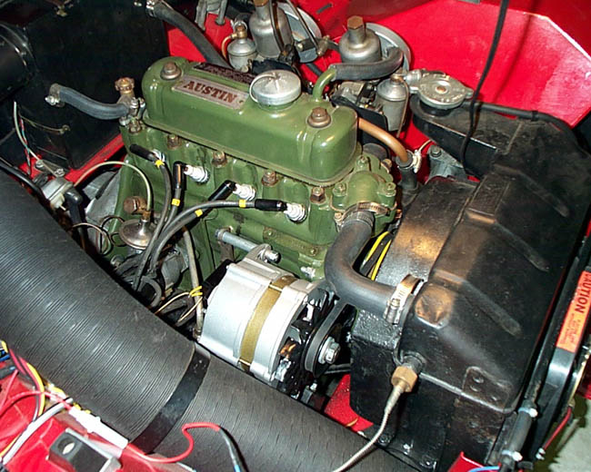
All in all, I'm quite happy with the results. I had feared that the alternator just wouldn't look right, but now that it's in place, it seems like a normal part of the engine. The voltage is up where it should be, the battery stays charged, and I don't have to worry when I turn on the headlights. A reasonable trade-off against original appearance, I think.
Disclaimer
I don't like saying this, but I suppose it's necessary, now that the lawyers have taken over American society. If you choose to do this, or something similar, but don't know enough about automobiles or electronics to be comfortable with it, get some help. In any case, I'm not forcing anyone to make this modification, so if you choose to attempt it, you take full responsibility for the results. This is just a report on my experience with these modifications. It is not intended to be a set of instructions for duplicating my work or a recommendation to do it. You're on your own.