Electronic Ammeter and Voltmeter
Steve
Maas
Long Beach, California, USA
July, 2007
 Early Austin Healy Sprites did not have an ammeter or voltmeter. Without
these essential instruments, it is impossible to monitor the operation of the
charging system. I found that my sprite, burdened with an extra electrical load
from an electric cooling fan, just barely kept the battery charged. My intended
solution to this problem is an electronic voltage regulator; however, it seems
obvious that, before changing the regulator, I need some way to monitor the
charging.
Early Austin Healy Sprites did not have an ammeter or voltmeter. Without
these essential instruments, it is impossible to monitor the operation of the
charging system. I found that my sprite, burdened with an extra electrical load
from an electric cooling fan, just barely kept the battery charged. My intended
solution to this problem is an electronic voltage regulator; however, it seems
obvious that, before changing the regulator, I need some way to monitor the
charging.
Conventional Ammeters
Most meters today are digital. They work by converting an analog voltage to a digital number, displaying that number on a digital readout. Conventional analog meters are still in use, however, and probably will remain so. (To see why, just try to adjust something for a peak or null value with a digital meter!) Conventional meters are based on the principle that a coil of wire carrying a current experiences a torque when placed in a magnetic field. The torque rotates the coil, and a pointer connected to the coil indicates the current. Such meters respond fundamentally to current; we call them current-sensing devices. Voltmeters consist of an ammeter with a series resistance, so the voltage is measured, by Ohm's law, as the current times the resistance.
Moving-coil ammeters can be remarkably sensitive. They are usually designed to operate at very low full-scale currents, because it is straightforward to extend their ranges to higher currents but not lower. Back when all test meters were analog, the "gold standard" was a movement that required only 50 microamperes for full-scale deflection. To measure higher current, it is necessary to use a shunt, a resistor connected in parallel with the meter so that it bypasses most of the current. The shunt resistance is given by the relation,
Rs = Rm * Im / (Ifs - Im)
where Rs is the shunt resistance, Rm is the meter resistance, Im is the meter current for full-scale deflection, and Ifs is the desired full-scale value of the shunted meter. This relation illustrates the problem in measuring high currents. If your meter has, say, a 1 milliamp movement (Im) and 100 ohms resistance (Rm), creating a 50-amp full-scale meter requires a shunt resistor of 0.002 ohms, the resistance of a decent-sized chunk of copper. Such a shunt can be made, of course, but a fair amount of care in fabrication and calibration is necessary.
Here's another problem. The meter I want to use is 1 mA full scale and has 700 ohms internal resistance. This meter would require a 0.035-ohm shunt. That shunt, at full-scale current of 20 amps, would dissipate 14 watts and would drop the system voltage 0.7V. That's a lot of lost power and, especially, enough heat that we'd need to think carefully about cooling. This just makes no sense; you shouldn't have to spend 14 watts to get a simple current reading!
The Ammeter
My ammeter uses a current sensor based on a Hall-effect device. The device puts out a voltage that is proportional to a magnetic field to which it is exposed. The magnetic field is created by the current from the battery, which passes through a wire wrapped around a large toroidal core. The Hall-effect sensor is mounted in a gap in the core.
There are a couple of important considerations in the design of the core. First, the core should be fairly large, about 1 inch in diameter, so that it is not saturated by the magnetic field, its hysteresis is minimal, and it can hold several turns of no. 12 wire. The permeability is not critical, but it should be reasonably large (100 or so), so the magnetic field is concentrated in the gap. The number of turns of wire on the core determines the range. The field strength should be such that the sensor output varies plus or minus about half a volt between current extremes; more, and it becomes significantly nonlinear. Getting this right is just a matter of experimenting: mount the sensor in the gap and adjust the number of turns of wire on the core until the range is right. The gap should be just wide enough to hold the sensor. The brittle core can be cut by a Dremel tool with an abrasive wheel.
The Hall-effect sensor is a 3503. It puts out about 2.5 volts when no magnetic field is present, and, in the presence of a magnetic field, its output voltage changes. Depending on the direction of the field, it may increase or decrease; thus, it can sense either charging current or discharging current at the battery. The output is linear (i.e., proportional to magnetic field intensity, which is, in turn, proportional to current) over a relatively narrow range, so there is a trade-off between accuracy and range. I therefore set it up for a relatively narrow range and use an amplifier to increase the voltage. The amplifier chip is an integrated circuit, a TLC274 operational amplifier. This "op amp" operates from a single positive voltage supply; most op amps require both positive and negative supply voltages. This makes the TLC274 ideal for automotive use.
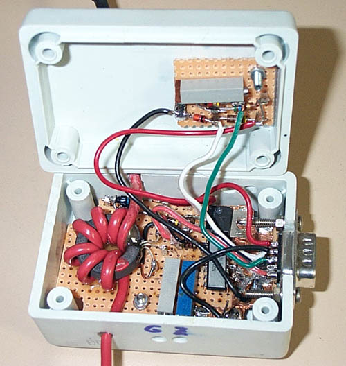
Below is a picture of the circuit mounted in a plastic box. Not all of the wiring has been installed, but you can see the toroid and other components. To see a larger picture, click on the thumbnail.
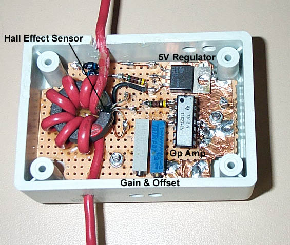
The rest of the circuit is simply for setting the correct amplification and offset voltage. Two potentiometers are used for this. Adjustment requires going back and forth between the two adjustments a little, but it is not difficult to get the circuit set up properly.
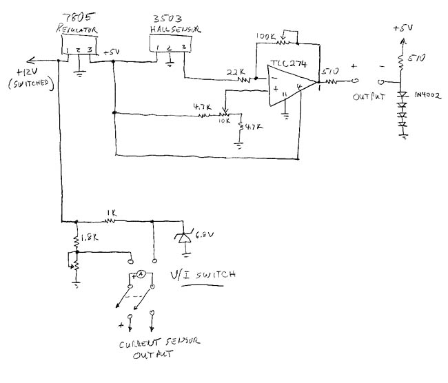
The schematic of the final circuit is shown below.
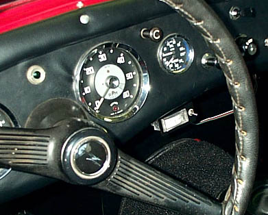
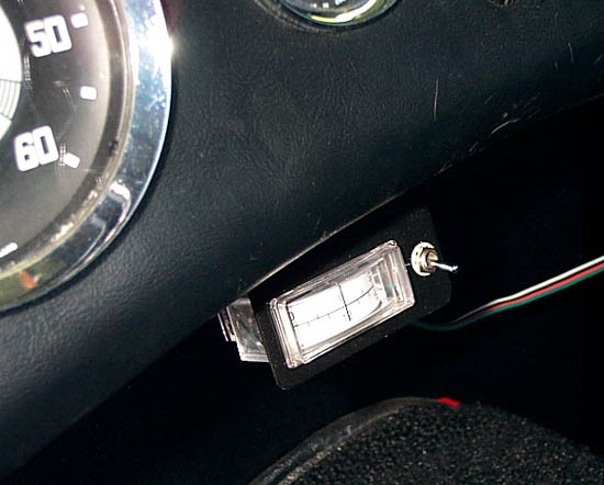
The indicator is an inexpensive 1-milliamp horizontal panel meter having approximately 700 ohms series resistance. The meter has a center zero position. I could have used a meter with the more common zero position at the left edge; it would have been simple to arrange the offsets so zero would be at the meter's center. However, the meter would then indicate -20A when the ignition was off, a situation that just didn't seem right to me. I made a new scale for the meter by printing it on a piece of card stock, then pasting it over the meter's 1-0-1 scale.
Finally, the sensor includes a simple circuit and a switch, so that either voltage or current can be displayed. The voltage scale is set up so 12V is at the center, and the range is 9 to 15V. A simple voltmeter would be OK for this, but the scale would read 0 to 15V or 0 to 20V, and that range does not provide the precision I'd like to have. The voltage-measurement circuit is shown in the schematic. The value of the 1.8K resistor depends strongly on the series resistance of the meter, so it should be viewed as a "select in test" item.
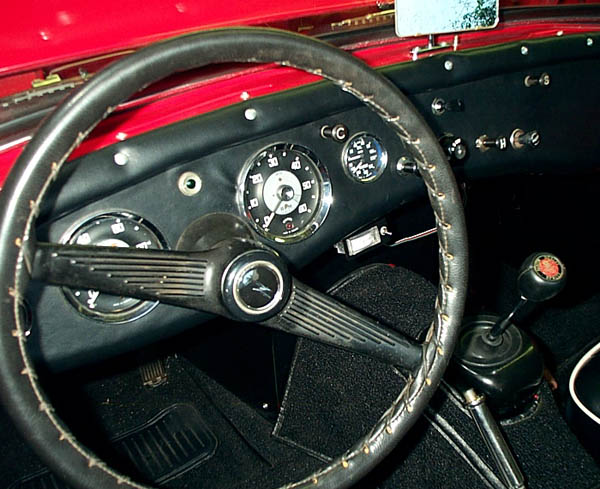
I don't want to hack a hole in the dash for the meter, so I need something that fits under the dash but stays out of the way. I made a simple bracket from sheet aluminum and mounted it under the dash, just to the right of the driver's seat. It is recessed behind the dash an inch or so. DC power comes from the switched and fused 12V power; the extra electrical load is trivial, a few milliamps.
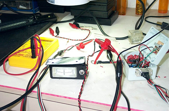
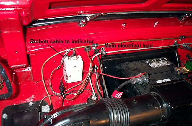
Below are pictures of the circuit in final form; in final test, before sealing the box; and mounted on the firewall.
Results
The wire through the sensor circuit has 0.0022 ohms resistance. (I determined this by putting 10 amps through it and measuring 22 mV across it.) This means that, at full scale current, it will dissipate less than 1 watt and drop the system voltage only 44 mV; this is a considerable improvement from the 14 watts and 0.7V that would be lost in a conventional shunt.
Watching the drain and charge current is illuminating. Because of my electric fan, the electrical load at idle is about 10 amps; with the headlights on, it's almost 20A. At idle, the generator produces very little power; clearly, you don't want the car to sit idling very long with a large electrical load. Another surprise was the difference between my digital voltmeter's indication and that of a moving-coil meter. My digital meter indicated voltages around 13-15V, but this meter indicated only 12-12.5V. It seemed that something was wrong until I checked the system voltage with a laboratory, moving-coil meter, and saw that it indicated the same voltage as my meter. The difference is caused by the different operating modes of the two kinds of meters. Digital meters sample and display repeatedly, never indicating a true average, while moving-coil meters indicate the average voltage. It would be interesting to look at the system voltage with an oscilloscope, but I'm almost a little afraid to do so.
Disclaimer
I don't like saying this, but I suppose it's necessary, now that the lawyers have taken over American society. If you choose to do this, or something similar, but don't know enough about automobiles or electronics to be comfortable with it, get some help. In any case, I'm not forcing anyone to make this modification, so if you choose to attempt it, you take full responsibility for the results. This is just a report on my experience with these modifications. It is not intended to be a set of instructions for duplicating my work or a recommendation to do it. You're on your own.