![]()
As I received the car, the electrical system was in horrific condition. The only real solution was to rip out the entire thing and build it up from scratch. The lights and other electrical parts needed both electrical and cosmetic restoration, as well.
Click on any picture to see a larger version in a new window.
Here is what I had to contend with. Would you like the job of sorting this out? I wouldn't, either. I just ripped it all out.

All the lamp sockets were in bad condition: old, worn out, dirty, and corroded. Previous owners jury-rigged things as the parts wore out, and of course that was not acceptable. The the trick to restoring the lights was to find an appropriate type of replacement socket. I rarely found perfect replacements, of course, but I found ones that were usable with minimal modification. I used the ubiquitous 1157 bulbs for the tail lights and front sidelights and 1003 bulbs for the license-plate lamp and the fog lamp. The headlights are ordinary sealed beams; at some point I might convert them to halogens, but not now. This kept everything simple and minimized the number of spares I have to stock.
The headlight chrome, like much of the car's chrome, was better than it looked. I buffed it with a medium abrasive and polished it, bringing back a lot of its original shine.


I primed and painted the headlight "buckets" and their supports.


I reassembled the headlights with new connectors and wire. Aiming the headlights on this car is pure simplicity; each headlight mount uses a ball and socket, with one nut to tighten it in place. Just wait until evening, turn on the lights, aim them where you want them, and tighten the nut. Done!

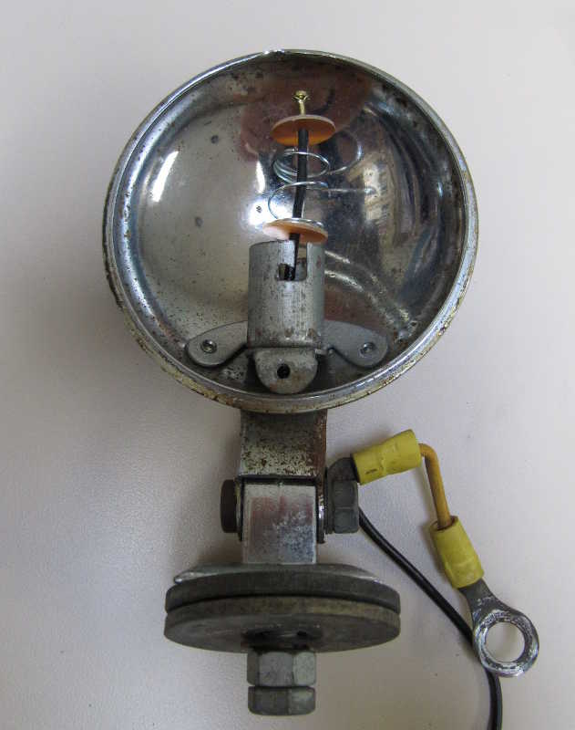
Restoring the fog light was especially satisfying. The electrical contact in the socket had fallen apart, and a previous owner had just taped it up. I was able to buy new innards for the socket, which fit perfectly. It's unusual for things to be this easy.
I buffed and polished the exterior and mounted the fog light on the car.


The socket I used for the tail lights is shown below, along with the original socket. I simply removed the mounting tabs from the new one, soldered it into the old one's (cleaned up) mounting bracket, and added a ground wire. Soldering to steel is not difficult if you use a high-wattage iron (I have a 200-watt gun) and a water-soluble, acid flux. The flux must be washed off completely after the part has been soldered, or the joint will corrode.


Fortunately, the lenses and bezels were in good shape, so restoring the outer parts of the tail lights was not difficult. Below are the restored tail-light parts. I painted the mounting plates with aluminum paint, washed the rubber covers and lenses, and buffed and polished the chrome bezels. They went back together with new hardware, and now they look virtually new.


The license-plate lamp was in bad shape. As I received it, the bulb was soldered to the wiring and hanging loose in the housing. I bought a new lampholder that takes the same type of bulb as the fog light (no. 1003), made a bracket for it, and soldered it to the holder. The bracket is screwed onto the back plate from the rear. The mounting studs on the back plate were badly rusted, so I drilled them out and replaced them with ordinary #10 screws, which I soldered to the inside of the plate. I cleaned and painted the back plate, buffed and polished the chrome cover, and put it all together.


The front sidelights were much like the other lights: lots of crud on the outside, rusty parts inside, and wires soldered directly to the bulbs. As with the tail lights, I installed new sockets and fabricated brackets for them. Buffing and polishing the outside brought back a lot of the shine. They're not perfect, but good enough.


I mounted the front sidelights on the fenders. This completes the lights.

I customized the wiring to improve the car's electrical reliability. I added relays for the lights and brakes, and I created a circuit using modern relays to replace the original turn-signal relays. I also added quite a few more fuses. The circuit is shown below.

Here is how it all works:
1. Relays 1 to 4 duplicate the function of the original TD turn-signal relay box. As I could not find small, double-pole relays, I had to use two single-pole relays for each of the turn-signal relays, left and right. Note that the two coils of the relays for each direction are connected in parallel, so they switch together.
2. Relay 5 controls the brake lights. The brake-light switch is notorious for wearing out quickly if it cuts the entire brake-light current, so this relay should extend its life.
3. Relay 6 is for switched power; that is, power that is turned on and off by the ignition switch.
4. Relays 7 and 8 are for the headlight high and low beams, respectively. They are implemented in the usual manner.
5. Relay 9 is similarly for the sidelights, front and rear, and the license-plate light.
The rest of the circuit is largely the same as the original wiring, except for a couple of details. First, I installed a beeper for the turn signals, so I don't forget to turn them off. The two 1N4004 diodes allow the use of a single beeper for both the left and right signals. Second, I added a fuse for the fog light. There is none for the fuel sensor, as the sensor grounds the line; if it shorted to ground, the only effect would be to turn on the fuel lamp, and no damage would be done. Third, I retained the original fuse block, just for appearances. The unswitched-power fuse powers only the horns; the other fuse is now unnecessary, but I installed it anyway, so it doesn't look strange. Finally, the diode in series with the ignition lamp may be puzzling. Without it, when the ignition switch is turned off, the generator can power the switched-power relay through the lamp and keep its coil energized; then the car keeps running when the ignition is turned off. The diode prevents that from happening.
The relays were mounted in a plastic box with the fuses on the outside for easy access. The pictures below show it under construction and finished. (The fuse block has 10A fuses in each location, which is obviously incorrect. I did this just for testing, and I installed the correct fuses later.) I tested it on my workbench before mounting it in the car. The large male connector connects to wiring from the dash; the female connects to the wiring harness. I made mounting brackets for the relay box and mounted it on the underside of the scuttle behind the battery box.


Because of the modifications, the use of a conventional wiring harness would have been problematical. Instead, I wired the car myself. The disadvantage was that I couldn't get multicolored wire, as was used originally, but as long as I documented the wiring well, I didn't expect it to be a problem. The advantage was that I could add fuses and relays, and I could upgrade the wiring. That's not unimportant, as the original wiring was inadequate in many respects.
I started by running the wires and cutting them to the correct length. I tagged all the wires and used masking tape to hold them in their temporary positions.

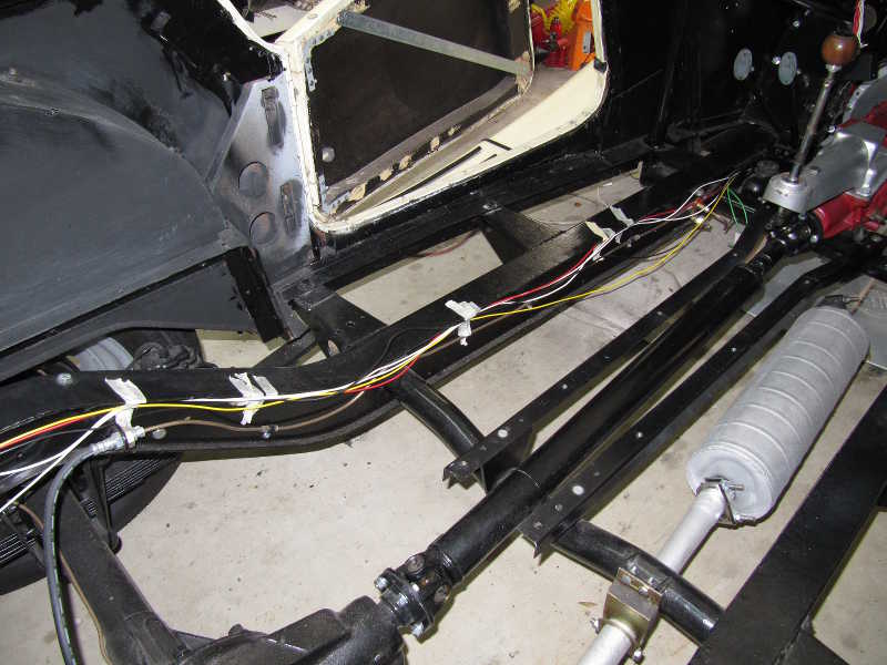

When all the wires were in place, I bundled them into some wire sheathing that looked at least somewhat like the original. (Don't worry, the zip ties around the brake line were just for temporary support.) At the ends, I supported the wiring appropriately. I left the tags on, as much as possible, until I'd tested it all.


I used cable clamps along the frame to hold the sheathed wiring in place. Instead of one big, fat harness snaked through the big hole in the scuttle, I have three smaller ones. The front lights on the left and right sides are separately bundled; a third bundle goes to the rear. Under the scuttle, as I complete the wiring, it looks like chaos, but it's actually all well organized.


I used a single-point ground so the electrics wouldn't depend on multiple unreliable grounds to a steel frame. The wiring continued to take shape, and once it was all in place, I tested it. It was satisfying to see all the lights and turn signals working. There was little more to do until the dash was installed.


I restored the instrument panel and wired it. The picture below shows it largely complete. The large connector connects to one from the relay box, and the two remaining holes are for the choke and starter controls. The complete story of the panel restoration can be found in the Interior Restoration section. Finally, I wired it into the car and tested it. Everything seemed to work just as it should.


Below are some pictures of the finished wiring behind the dashboard. I used the frame hoop to support the wiring and added a cable clamp to the side of the glovebox to support the large connector. The panel grounds were connected to the car's common ground point.


I cleaned and readjusted the voltage regulator. The contacts looked good, which is what's most important. I did the mechanical adjustments as described in the service manual and the electrical ones using a voltage-adjustable laboratory power supply. The adjustment is not difficult; most important in the mechanical adjustment is making sure that the relays close and open with a crisp, fast snap. After that, it's easy to make them close or open at the right voltage.
I suspect that the numbers 8-52 on the back are a date code. It's probably not original (the car was built in late 1951), but instead is an early replacement. The old regulators are much better than the modern ones, so I decided to keep this one.


The horn mounting brackets were cracked, so I had to make new ones. They were mounted, like the originals, with rubber isolators. I restored the horns and readjusted them.


