![]()
Engine Rebuild
OK, admit it: you haven't read anything else on this site, but once you saw the link to the engine rebuild, you came here directly. This is no criticism; I'd have done the same thing. Everyone is interested in engines, but they shy away from the other major mechanical parts, transmissions and differentials, probably because they are reputed to be difficult to understand and to work on. But the latter, I think, are at least as interesting, maybe more so.
Although compression tests reportedly were good, it was clear that the engine hadn't been opened for quite a while, so this clearly was the time to check it out. There were plenty of external indications of things that needed to be sorted, such as incorrect head studs, missing or broken screws and nuts, and so on. It was no surprise that I found more as I dug into it further. The engine, as it turned out, showed no signs of abuse or neglect, but it was well worn and clearly due for a rebuild.
Click on any picture to see a larger version in a new window.
Contents
- Engine History
- Cleaning, Disassembly, and Evaluation
- New Parts
- Machine Work
- Measurements
- Preparations for Reassembly
- Engine Block Reassembly
- External Components
- Cylinder Head
- Finished Engine
- Valve Timing
Engine History
The engine serial number matches the number on the Heritage Certificate, so it is undoubtedly the original engine.
The extra parts that came with the car included the set of standard-size pistons that were replaced in the last rebuild, stored in the box for the AE pistons that I removed from the engine. The standard-size pistons were clearly factory parts, marked with the Triumph part number and the size code F. The box was stamped with an apparent date code from 1971. This indicates that the engine probably was rebuilt only once, in 1972 or 73. The condition of the engine, and the previous owner's report that the car had not been driven much in the past 20 or 30 years, is consistent with that.
As noted below, the cylinder head had been replaced by a TR4 head. The TR4 and 4A heads are almost identical and completely interchangeable, so switching heads probably was a quick and inexpensive fix for some kind of problem. Although I had the original head, it was not rebuildable, so the TR4 head was rebuilt and used.
I suspect that the camshaft was replaced sometime after the previous rebuild. Its condition was just too good for it to be very old.
Cleaning, Disassembly, and Evaluation
The engine sat in the corner about four months; I started working on it while waiting for transmission parts to arrive. Like most of the other parts, the engine was unspeakably cruddy. I started by giving it an initial cleaning, removing parts that were in the way. The usual process: scrape off as much crud as possible and wash the engine with solvent. A messy, joyless task.
At this point, it was futile to try to clean the engine perfectly; I just wanted it good enough to work on. The individual pieces, as they were removed, got cleaned more completely.
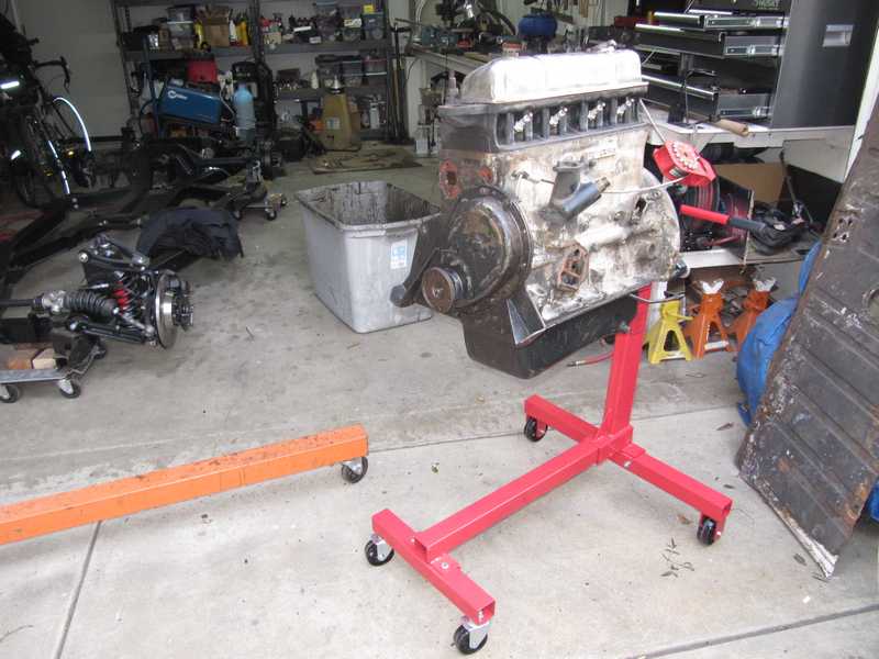
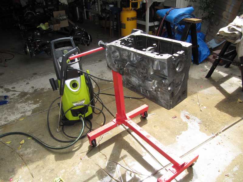
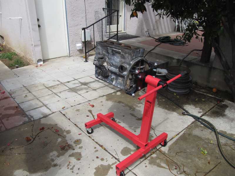
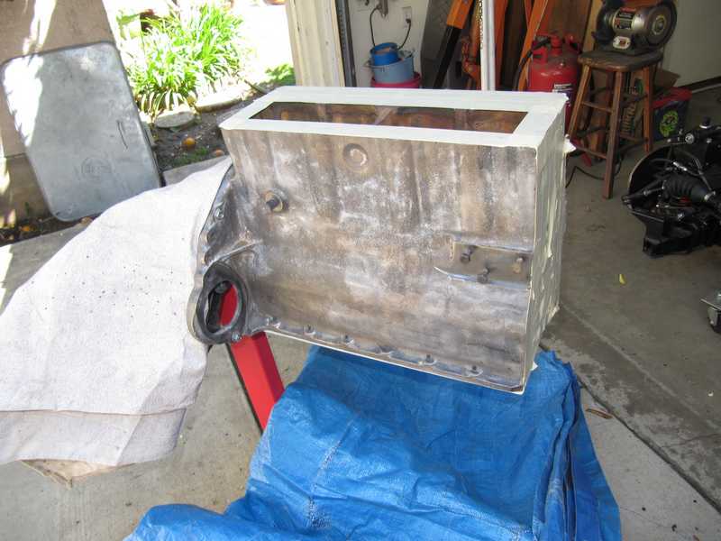
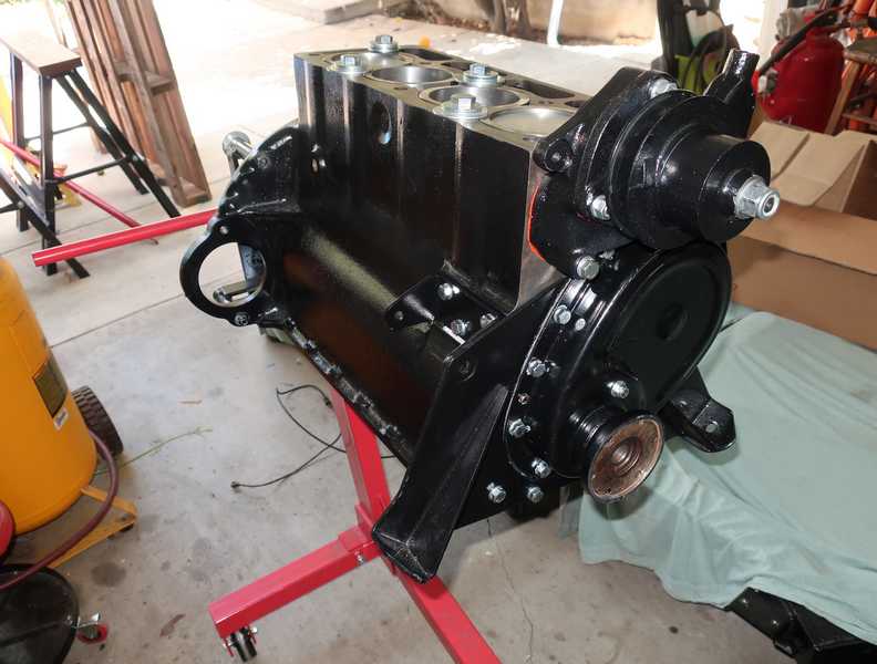
With the engine somewhat cleaner, I mounted it on the engine stand.
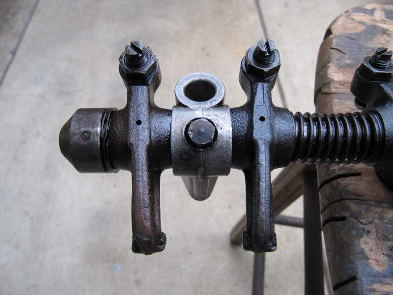
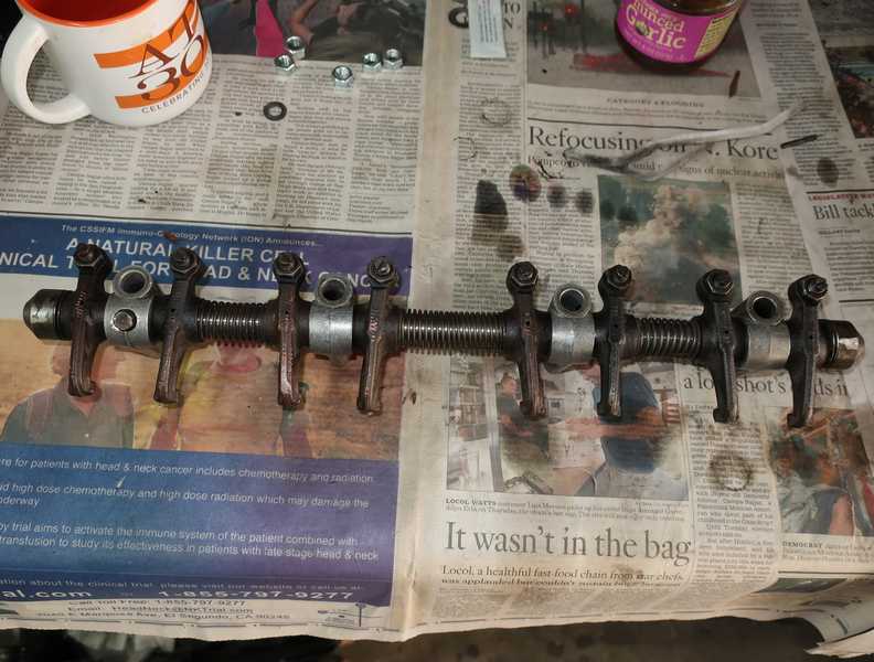
Once it was on the stand, I could start taking it apart. Up to this point, I hadn't even taken off the valve cover. I was hopeful when I saw oil pooled on top of the head, showing that oil was getting to the rockers as it should. At first appearance, the rockers seemed almost new, but later it became clear that they were not. Below, the engine with the rockers removed and the oil sopped up.
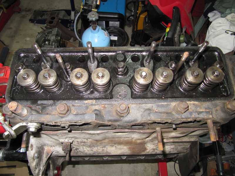
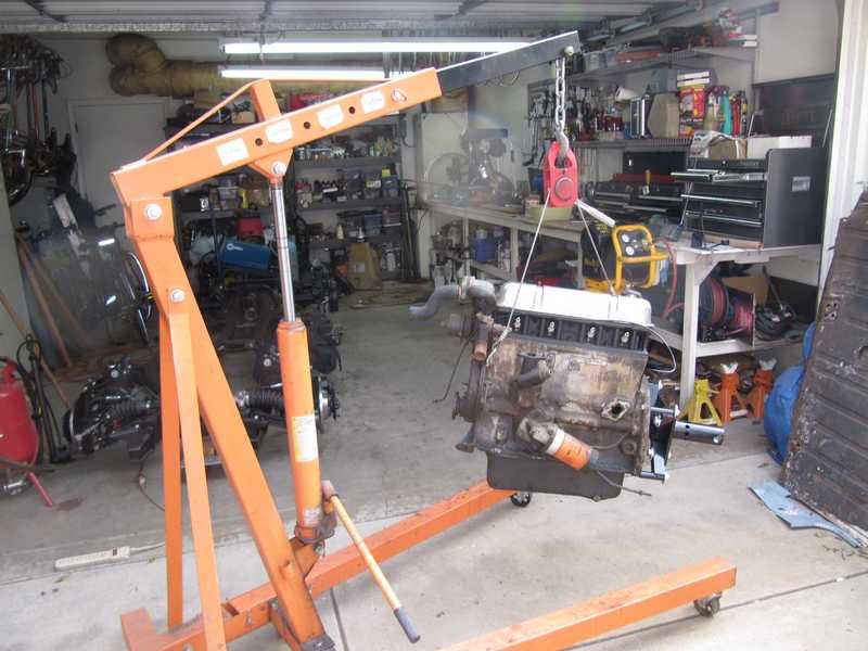
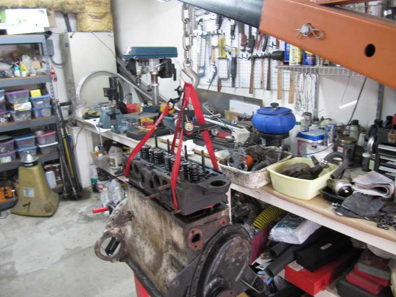
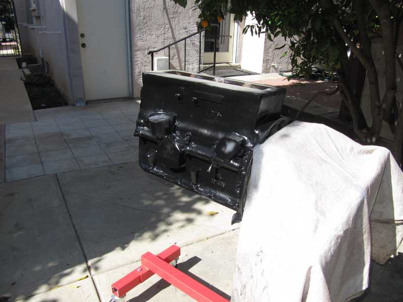
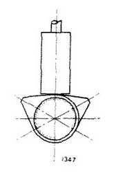
The cylinder head, as they often are, was a bit recalcitrant. I used my crane to lift it off, thus using the engine's weight to help separate the head from the block.
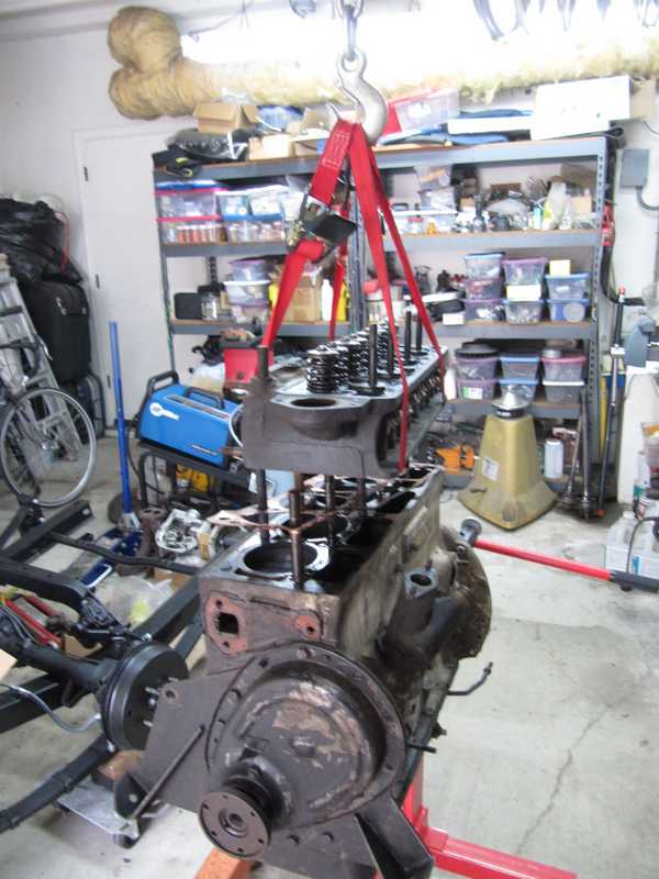
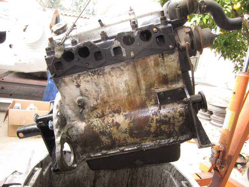
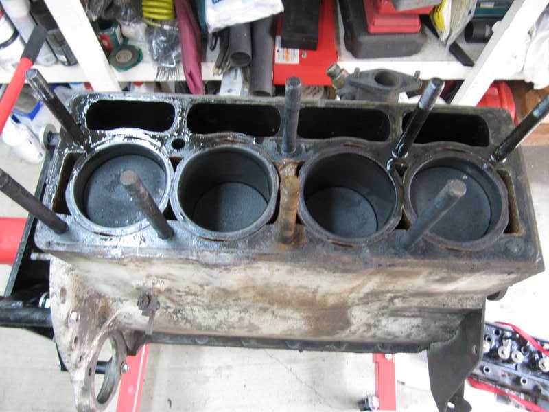
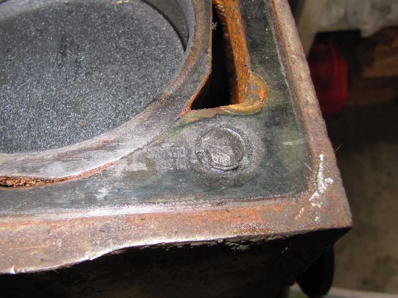
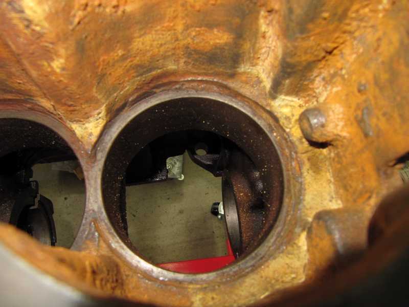
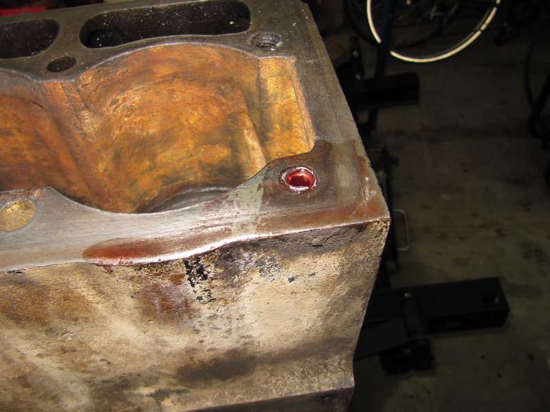
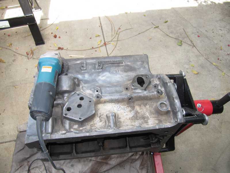
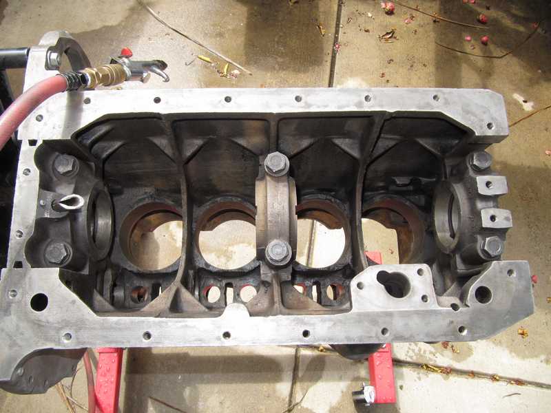
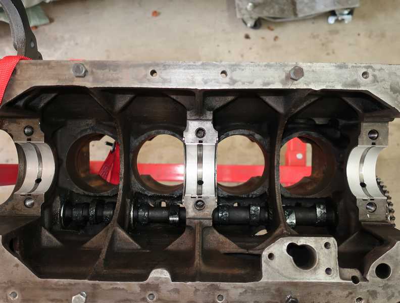
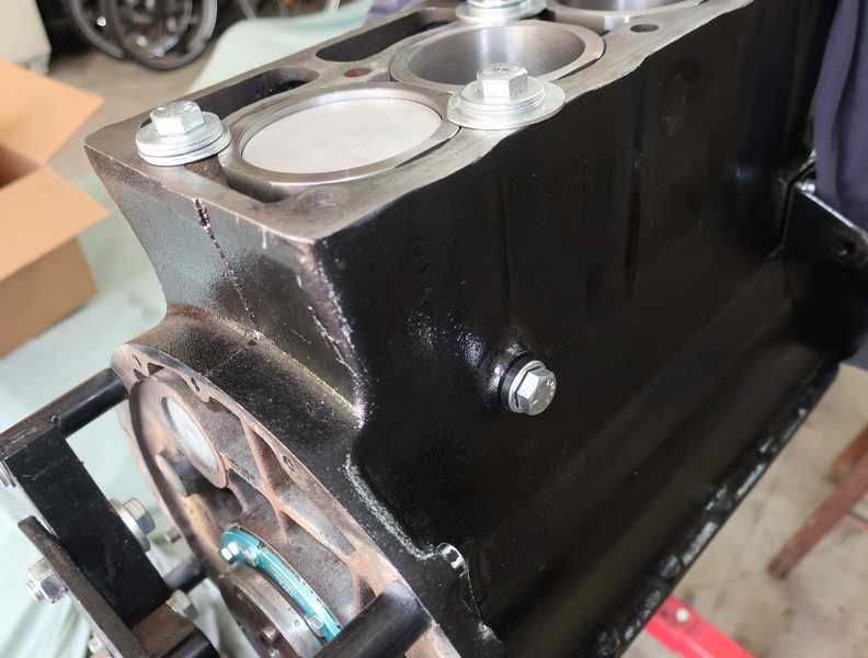
With the head removed, the block looked pretty normal, all in all, for an old engine. The stud in the right front corner was clearly too long and was rusted into the head. Turns out it was broken, as well. I wondered if it was replaced at some point, with whatever the mechanic had available, and it broke again. Whatever the story, the remains had to be removed.
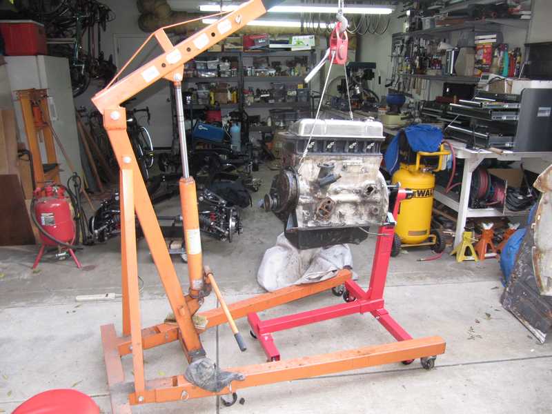
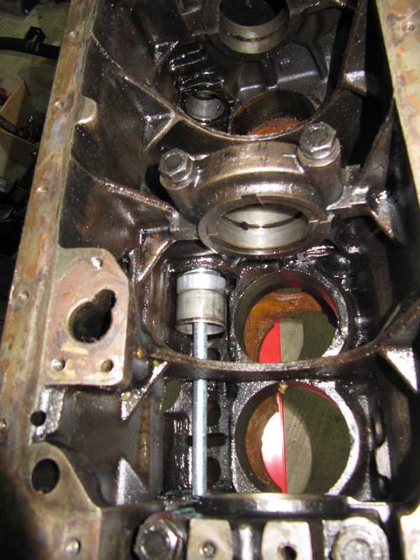
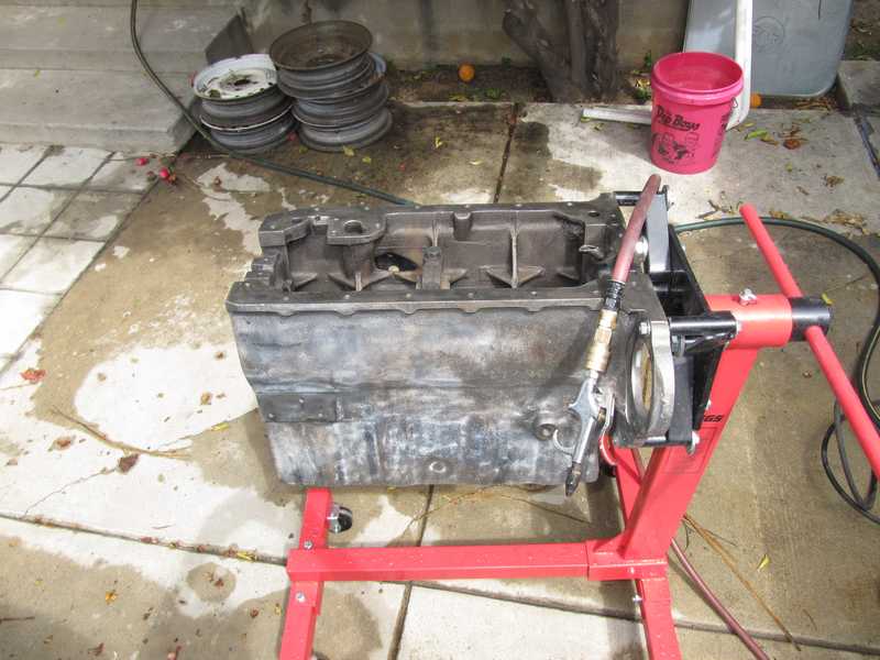
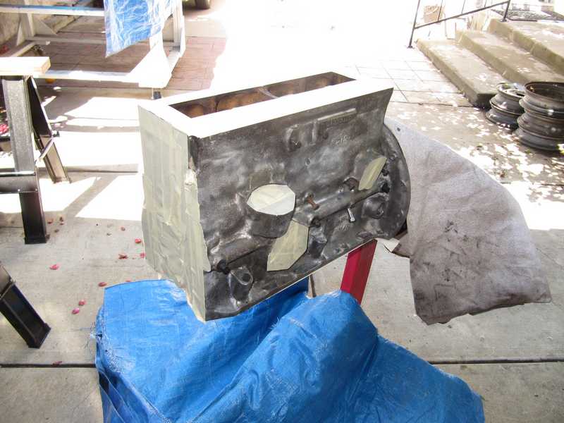
Here is the underside of the engine, cleaned up a bit and ready to be disassembled. The oil pump and pickup have already been removed.
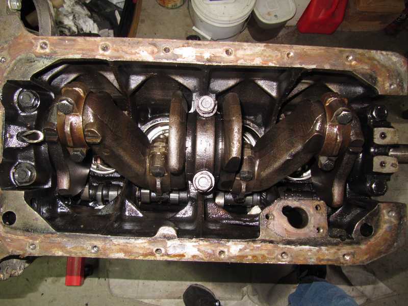
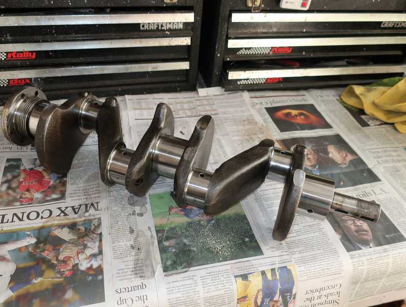
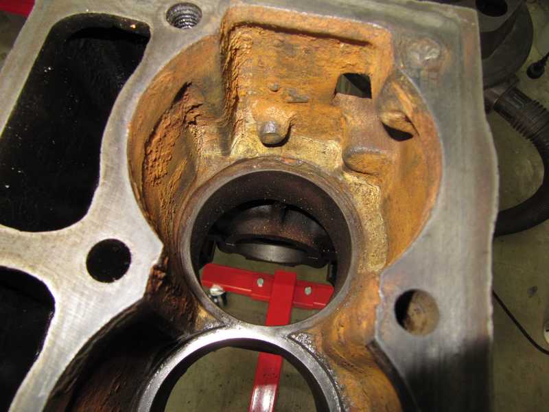
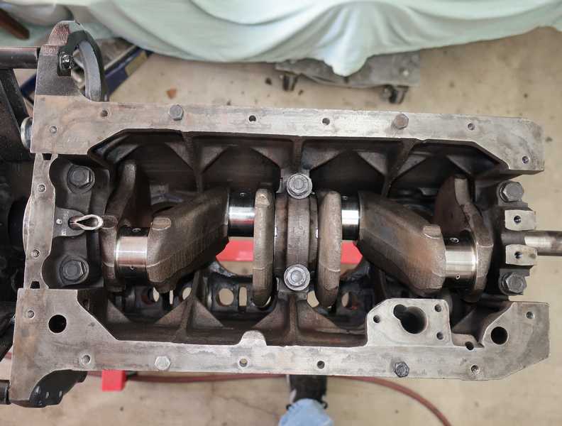
Removing the rear bearing cap required a simple puller. I rigged one from bits of my bearing-puller kit and some other hardware. With the caps off the main and rod bearings, the crank was ready to be removed.
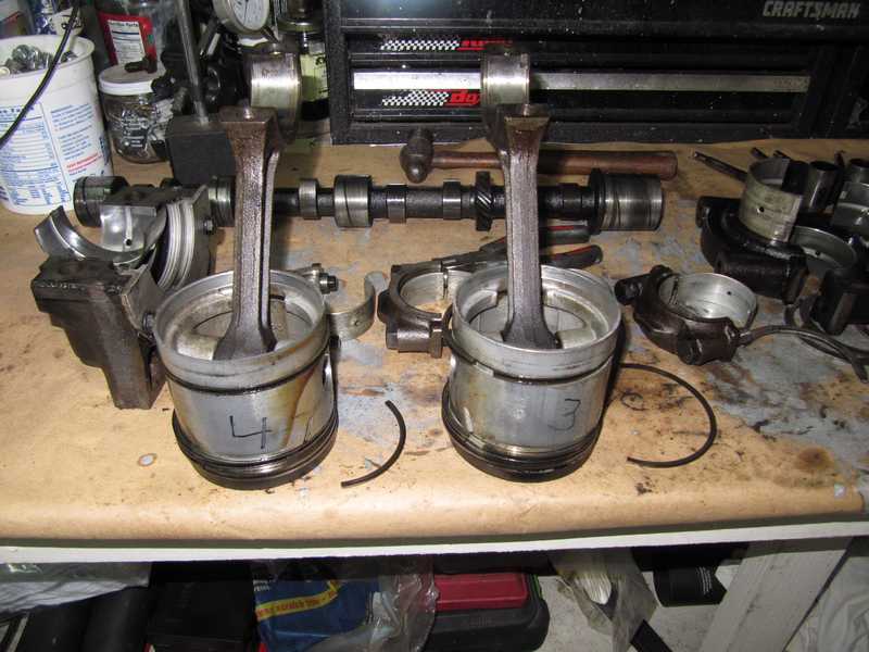
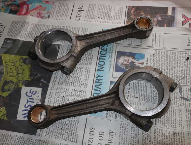
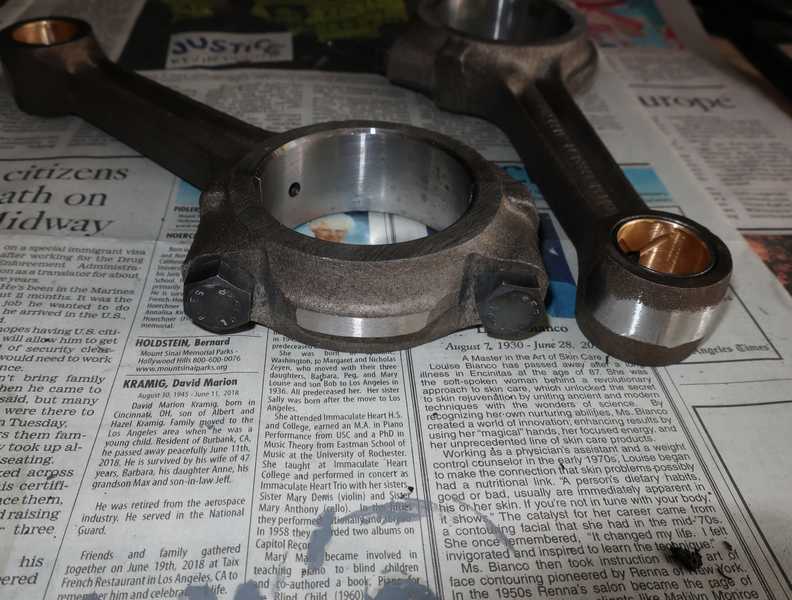
Below, a rogue's gallery of engine parts. I found broken rings on two of the pistons. Not a big surprise, considering their age.
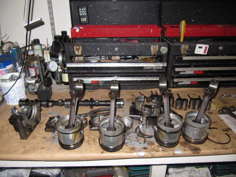
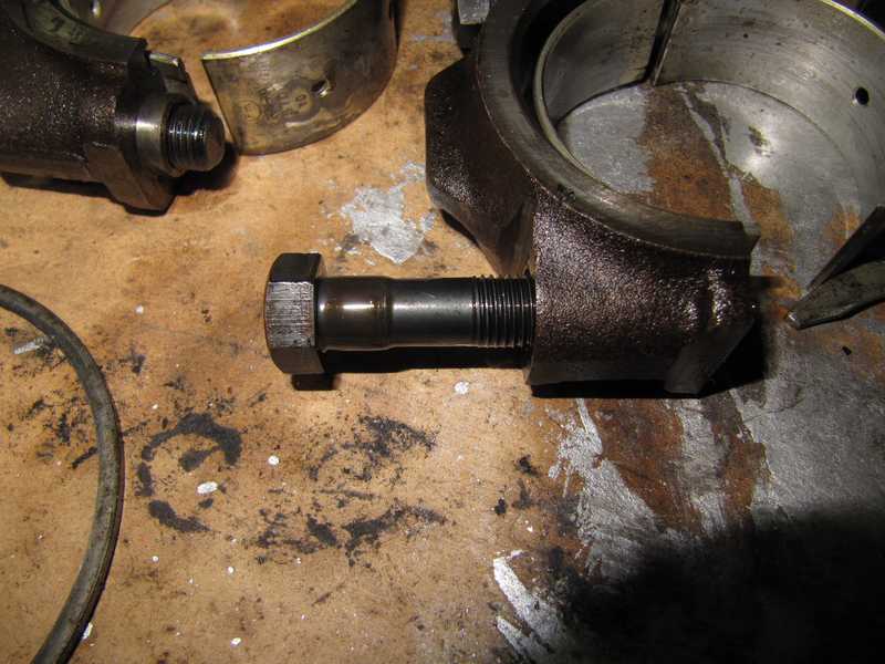
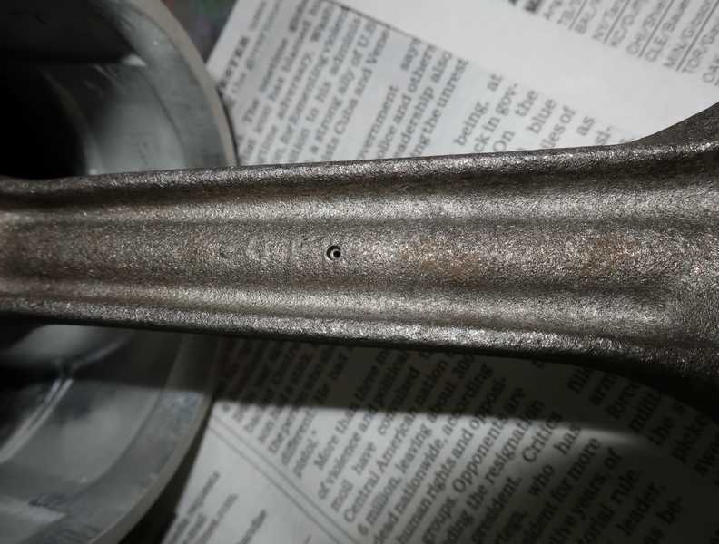
The picture below shows one of the famous TR4A connecting-rod stretch bolts. They all were replaced; in any rebuild, their replacement is essential.
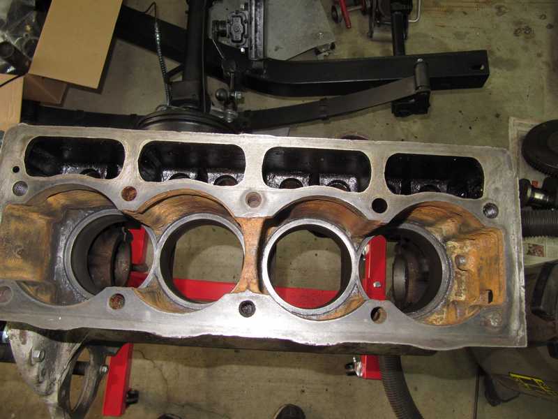
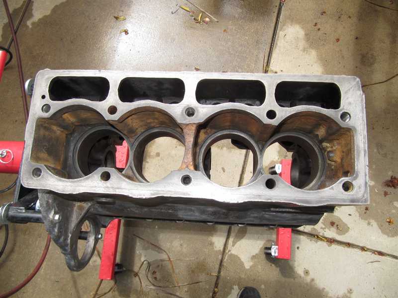
I measured the cylinders and found that (1) they were bored 0.030 over, and (2) the taper and ovality were well out of spec, both reaching 4 mils in places. When I started on the engine, I hoped it would need only a refresh with bearings and rings, but it had become clear that a full rebuild would be necessary.
![]()
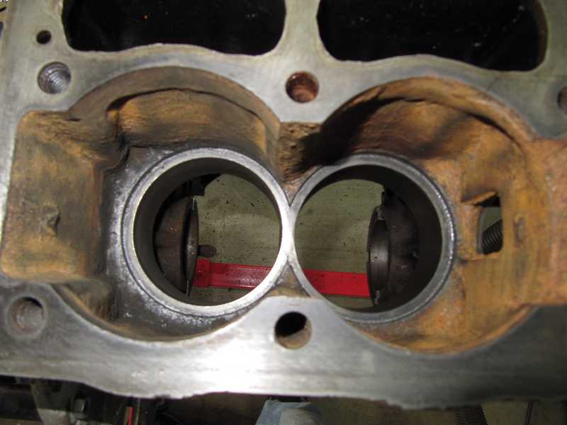
I tapped the cylinders out with a hammer and a block of wood. The rust in the water jacket around the cylinders was significant, especially behind the last cylinder, where the coolant doesn't circulate well. The rust actually filled the space between the cylinder and the rear wall of the block. That cylinder turned out to be the one most severely out of round. Go figure.
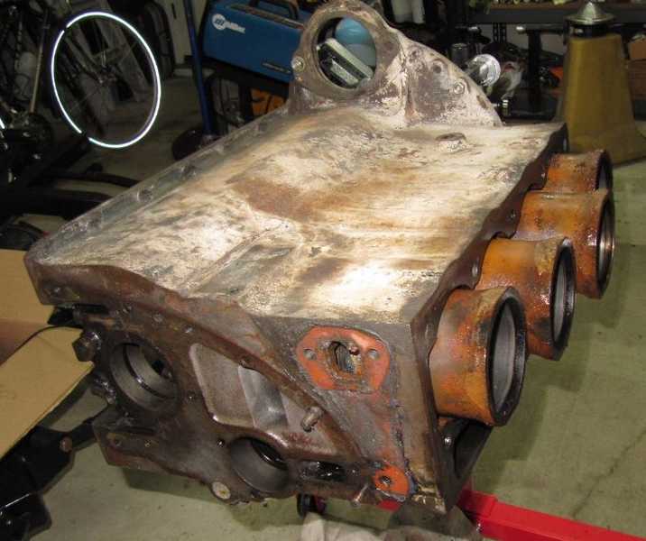
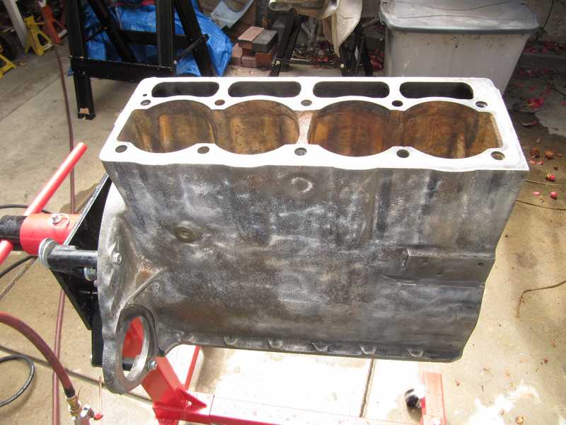
The block was rusty as well, but not to a disturbing degree. This is just what old engines do.
The camshaft looked really good, with no corrosion evident on any of the lobes. The journals were within spec. I saw no reason to replace it.
Some of the tappets showed, at worst, very light corrosion. Notice the light, circular wear marks on the ends of the tappets. That's a good sign. The cam lobes are located slightly off the center of the tappets, so the tappets rotate a bit with every cam revolution. That evens out the wear and extends the life of the tappet. The circular marks show that the rotation was occurring as it should.
I probably could have continued to use these tappets, but, instead, I got a set of special, hardened ones.
Similarly, the tappet ends of the pushrods showed minor wear and probably could have been reused. I replaced them anyway.
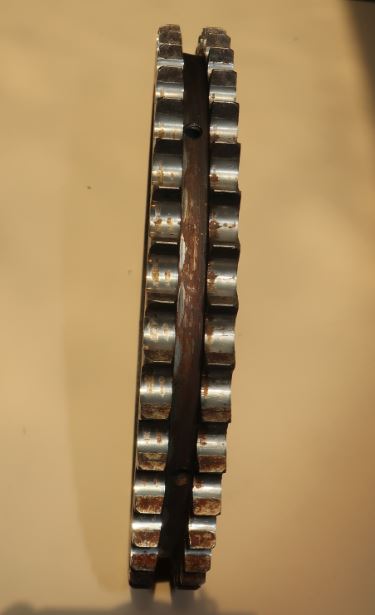
The timing gears showed light corrosion; you can see it in the hollows between the gear teeth. The camshaft gear (left picture) was the worst, but the crankshaft gear also wasn't perfect. While it's wise to be judicious about replacing parts that are in usable condition, as the quality of new parts often is poor, I still chose to replace these. They are approaching the end of their lifetimes, and the new ones are well made and inexpensive.
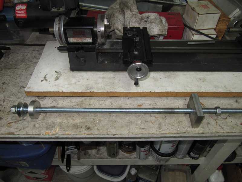
Here is my cam-bearing removal tool. It consists of a length of 1/2-inch fine-threaded rod, two aluminum pieces, and some washers. The round aluminum piece is 1.830 inches in diameter, 1/2-inch thick, and the square piece is approximately 1 1/2 x 3 x 1/2 inches. It presses the bearings out nicely.
New Parts
In this section I'll show some of the more interesting new parts.
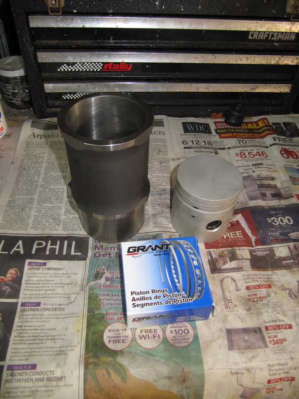
I bought a new cylinder set from Rimmer Bros. in the UK. Although similar sets are available in the US, this one was cheaper from Rimmer, even with shipping costs, and, at the time I ordered it, most local suppliers were out of stock. The quality is nice: County pistons and liners, and Grant rings. (The piston set I bought for my second engine used Hastings rings; I decided that I liked them better.) A lot of the suppliers in the US don't even state the brand in their catalog listings.
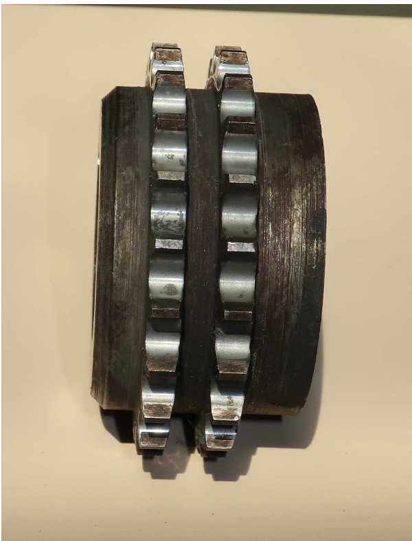
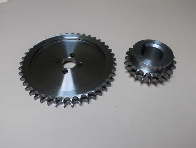
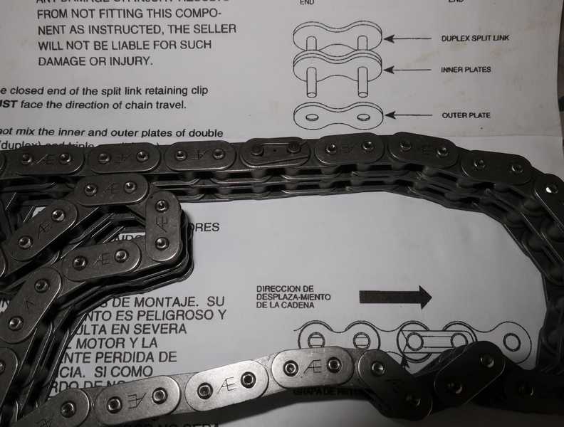
Here are the new timing gears. They are well made and surprisingly inexpensive. Next is the AE timing chain I bought to go with them; it's a nice part, also surprisingly cheap.
 \
\
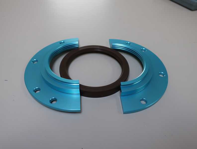
The following picture shows the new rear crankshaft seal. This replaces the original, marginally effective scroll seal.
The only ARP hardware made for the TR4 is this set of studs, which I purchased. If they produced rod bolts or tappets for my car, I would have bought them, too.
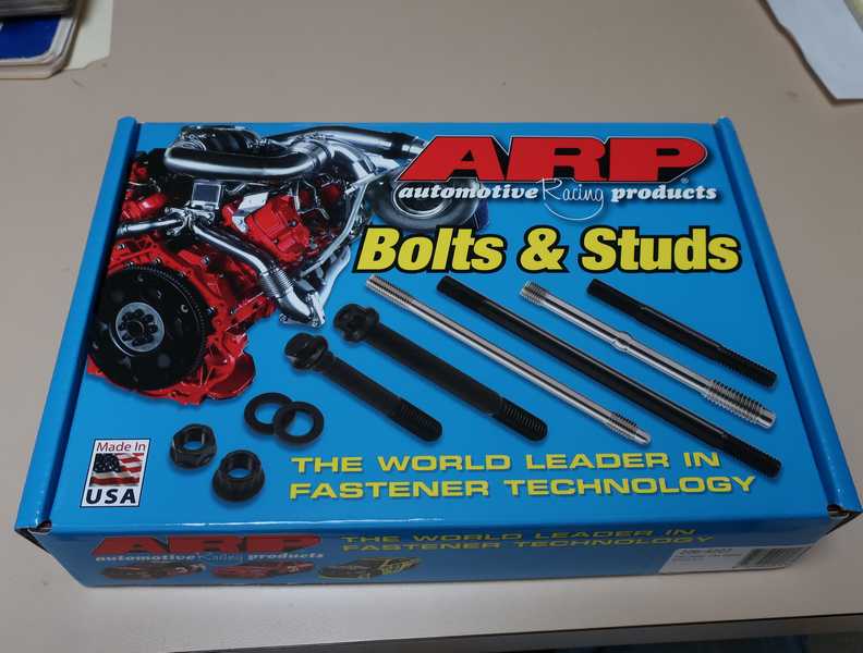
Digression on Head Studs: Head studs are expensive. This kit cost $130, and a set of studs from the Usual Suspects costs about the same. Why not just reuse the old ones?
The studs are 1/2 inch in diameter, fine threads at the top and coarse where they thread into the block. The specified torque is 100 to 105 lb. ft. With ~0.15 coefficient of friction, I calculate the axial force on the stud as 13,000 pounds at maximum torque; that gives a stress of 100,000 PSI. Grade 8 fasteners have a minimum yield strength of 130,000 PSI, so this is coming pretty close to the limits of standard hardware in good condition. And, as standard replacement parts probably come from some nameless supplier in India or Indonesia, I wonder if they can be trusted to meet even that standard.
Another consideration is the fatigue limit, sometimes called the endurance limit, a stress level above which the fastener can be damaged by fatigue. I have no data showing that limit for grade 8 fasteners, but for steel it is typically about half the tensile strength, which, in this case, gives a limit of about 75000 PSI. Thus, these studs are used at stress levels where they are subject to some degree of fatigue, and it's a safe bet that used studs have been weakened somewhat by fatigue. Furthermore, long use has left the studs with scratches and rust areas, which create stress risers, where fatigue is even greater; then, cracks can form, leading to failure. In view of these considerations, it seems foolish to reuse old studs.
The ARP studs have a rated yield strength of 200,000 PSI. This not only means that they have greater strength, but they also are likely to have a higher fatigue limit, so fatigue damage should be less. But, whether the choice is for the ARP studs or conventional, new studs should be used in any engine rebuild.
Machine Work
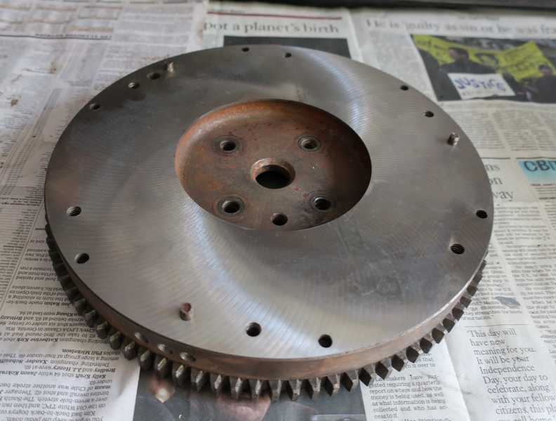
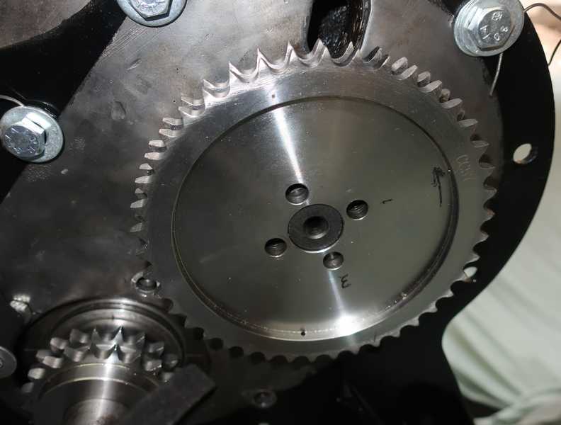
I had the flywheel resurfaced and balanced. You can see three drill holes, in the forward edge, where metal was removed for balancing.
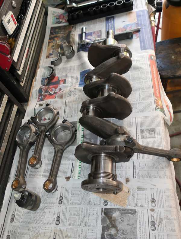
Below is the crank, which was ground 0.010 undersize and balanced. The bright areas on the counterweights show where metal was removed for balancing. I checked the journal diameters, and they were right on.
The big ends of the rods were honed to their correct size, and bushings in the small ends were installed and reamed. The rods also were balanced, as were the new pistons. You can see where metal was removed from both ends.
I love nicely done machine work. I could stare at it for hours.
A Later Note
When I finally got the car on the road, the value of a good balancing job became apparent. The engine runs as smooth as a baby's butt, and spins up to red line seemingly effortlessly. I'm happy I had it done.
Measurements
The cylinder protrusion above the deck is reputedly a critical dimension. The spec is 4 mils ± 1 mil , not a lot of room for error. In fact, the tolerance is so small that I have to wonder if it was regularly met at the factory. As long as the cylinder mounting flange depth was correct, and the cylinder itself was within spec, the protrusion should have been OK. But all those parts have a tolerance, and even ±0.5 mil on each allows up to 1.5 mils variation from the desired protrusion.
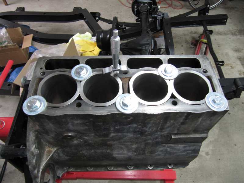
Before I could check it, I had to clean up the cylinder mounting surfaces. The surfaces had a deposit, probably old sealer and rust, which would have prevented new cylinders from seating. Below is an example, cylinder no. 1. In the picture, it looks like rust, but it's not; it's actually black and crumbly, like carbon, colored by the rust deposits.
I was able to remove the deposits easily with a small hammer and chisel. That sounds brutal, I know, but it required only light tapping to chip them away. That did not scratch or nick the mounting surface at all. Using a collection of wire brushes in an electric drill, I also removed loose rust from the inner sides of the block.
The first figure below shows cylinders 1 and 2; 2 has been cleaned up. The next shows 3 and 4, which have been cleaned as well. There was a large glob of the deposits against the rear wall of the block; I chipped it out easily. The third picture shows all the cylinders, finished. The outer edges of the mounting surfaces are a little pitted, but the gasket does not sit on them; its diameter is somewhat smaller than the outer diameter of the mounting surface.
Now to check the cylinder protrusion, which is specified at 3-5 mils. Experienced TR people will tell you that this is a critical dimension, but I found that the tolerances of the parts, especially the figure-eight gaskets, makes it difficult, if not impossible, to obtain that kind of precision. Here's the problem:
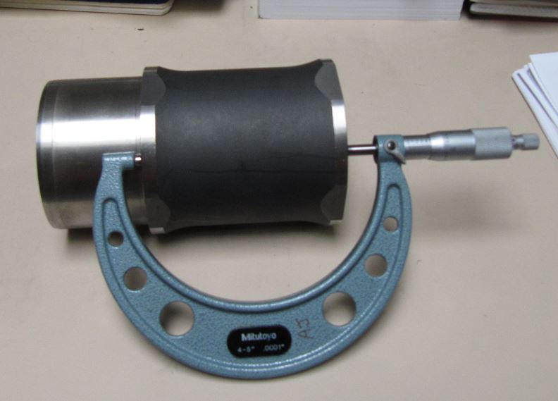
- The flange depth below the deck was 4.500 ± 0.001 inches, measured with a depth micrometer and a precision "123" block (as the micrometer didn't have enough range).
- The flange depth of the cylinders was 4.486 ± 0.001 inches, measured with a 4-5 inch micrometer.
- The cylinder set came with 15-mil steel figure-8 gaskets, but I also bought a set of 20-mil copper ones. All of the gaskets had burrs on their edges, which I removed, but they nonetheless were a little irregular. Deburred, the 20-mil copper gaskets measured 19-20 mils; the 15-mil gaskets measured 15-16 mils thick.
- The gaskets were not perfectly flat, having some small but significant imperfections.
So, if everything was perfect, 20-mil gaskets should have given 6 mils protrusion. Variations, however, were ± 1 mil for each of the measurements, giving ± 3 mils, or 3-9 mils of protrusion, exceeding the 3-5 mil spec. But even with the bolts shown below, which provided some needed compression, I measured up to 11 mils protrusion! I suspected that most of the error was caused by local irregularities in the rather poorly made gaskets, plus tolerances that were mostly on the side of greater protrusion. Even so, I saw several mils more than I would have expected.
With the 15-mil steel gaskets, I measured 3-5 mils protrusion at most points around the cylinders' circumference, most points closer to 3. The thickness measurements predicted something closer to 1 mil. Although the protrusion seemed good, it bothered me that it still was greater than the predicted value; it seemed likely that, once the cylinders were compressed by the head, the protrusion might settle to a value too low to provide sealing.
(In the past, gaskets of various thicknesses were available, so a gasket could be chosen to meet the spec precisely. Not any more. Occasionally, though, people have made their own gaskets from shim stock.)
In the end, I used the copper gaskets, sanded down a couple mils. More on this in the Reassembly section.
This measurement did not include sealer, of course, which must be used on assembly. I expected it to add a mil or two to the protrusion, but, in the end, it caused no measurable increase. That's probably because the gaskets were still a little irregular on installation, so the sealer was squeezed out of the high areas and into the low areas (which is, in fact, what we want). In my second engine, where I succeeded in flattening the gaskets better, the sealer introduced about a mil of additional protrusion.
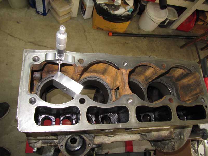
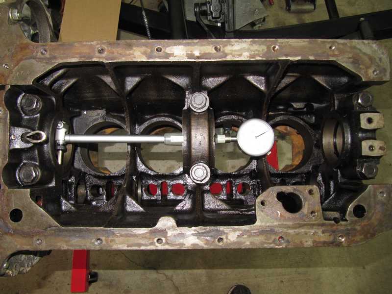
I measured the main-bearing bores. They were within spec, a mild surprise, as the maximum allowed ovality is only half a mil. This obviated any need to take the block to a machine shop.
Preparations for Reassembly
Removal of the Broken Stud
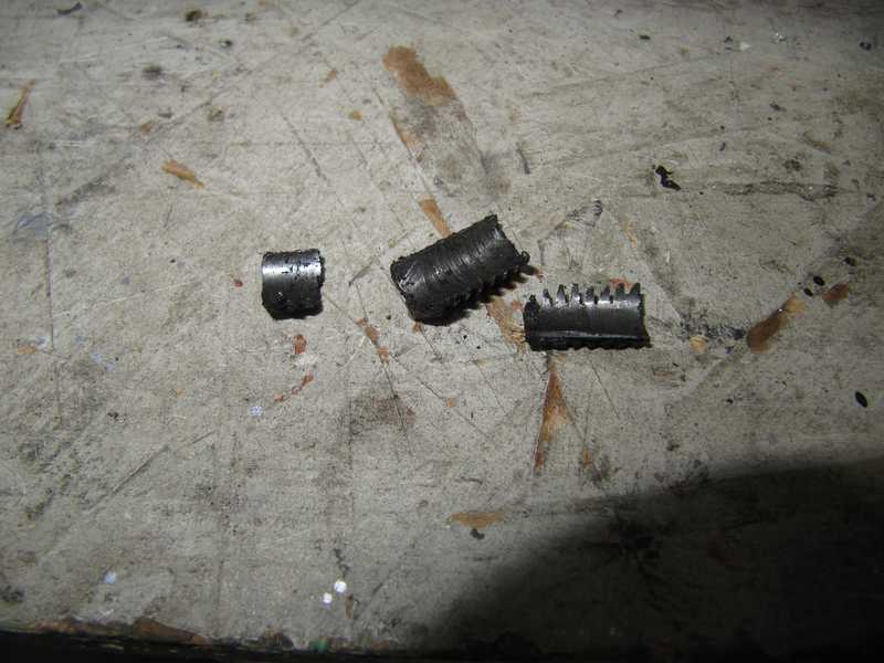
Optimistic soul that I am, I tried to remove the broken head stud with an extractor. I drilled the stud, all the way though it, for my largest extractor, filled the hole with "weasel pee" (the world's greatest penetrating oil, a 50-50 mix of acetone and automatic transmission fluid) and let it sit for a few days. I had to refill it periodically as the acetone evaporated.
No luck using the extractor, big surprise, so I drilled the stud. I used progressively larger drills until the hole was as large as I could make it without damaging the threads; then, I broke the stud off inward with a chisel and a punch. Below, the remains of the stud.
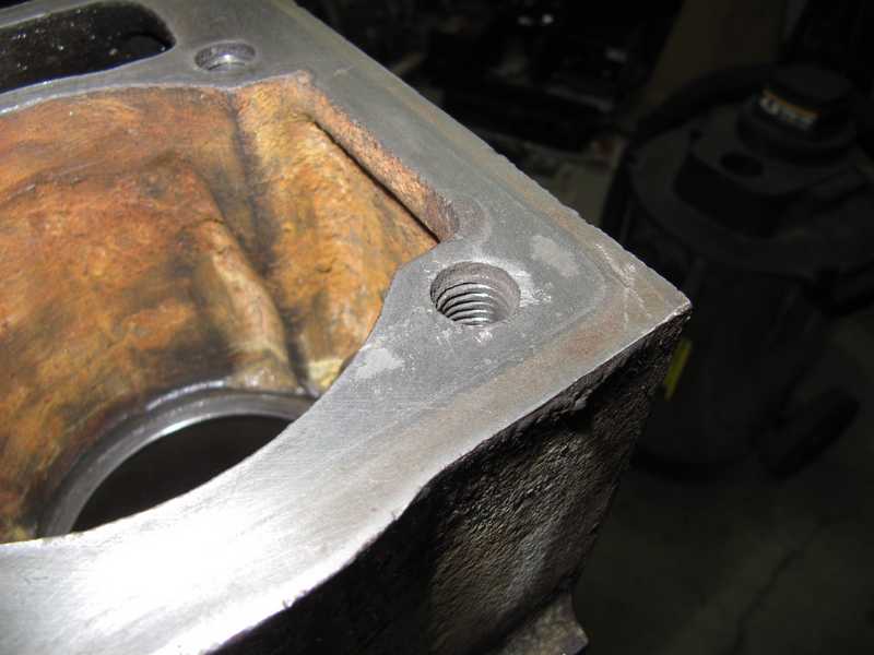
After removing the pieces of the stud, I chased the hole with a tap (1/2 UNC). There were a few minor scratches around the hole, which I took out with a little sanding.
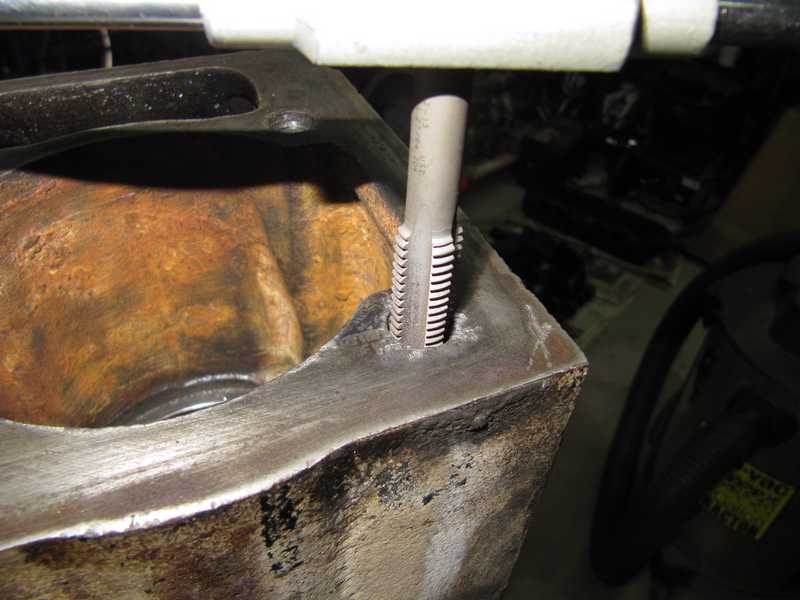
I found this to be the most consistently successful way to remove broken screws and studs, although it entails some risk of damaging the threads. It also requires that at least a little of the stud protrude above the surface of the block. Several of the engine block's holes for head studs were quite deep,with threading at the bottom; I don't have any good solutions for a tight stud that is broken off in one of those holes. I'd have to take it to a machine shop that could deal with it.
I chased all the holes in the block, especially the ones for the cylinder-head studs. Because of the holes' depth, I bought an extra-long, half-inch UNC tap to chase them.
Cleaning and Preparation for Painting
Since my measurements showed that the block didn't need any work, I got it ready for painting and reassembly. First, I washed it with naphtha. Then, when it was dry, I took off all the old paint with a wire brush on an angle grinder. Finally, I washed it with strong detergent in a pressure washer and dried it with compressed air and towels.
I took care to blow out all the oil passageways and to make sure that the unprotected steel surfaces were completely dry. I also flushed the oil passages and blind-tapped holes with carburetor cleaner.
I let the block sit in the warm sun and breeze to dry completely.
Painting the Block
At this point, the block was ready for painting. I chose to paint it black, its original color. using ordinary, rattle-can, Duplicolor engine paints for both the primer and finish coats.
Below, the block is masked for painting. I put screws and rubber plugs into the various holes to prevent paint from getting into them. I didn't plug the holes for the oil pan, because they were easy to chase, and any paint flakes removed by chasing could easily be kept out of the inside of the engine.
First, a coat of primer.
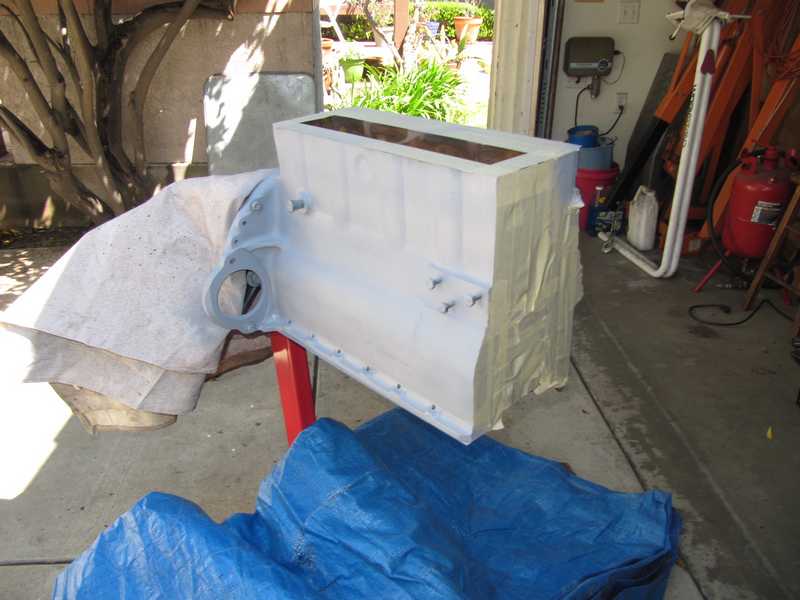
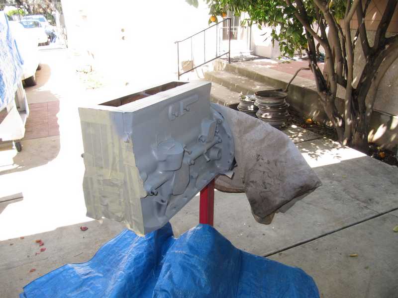
And, finally, a finish coat of black paint.
Some people don't paint an engine until it is completely assembled; then, they spray the whole thing, bolts and all. I know that, in some cases, engines were painted that way at the factory, but I don't think it looks good. It also creates a mess if you have to remove a bolt.
Engine Block Reassembly
Crankshaft and Connecting-Rod Checks
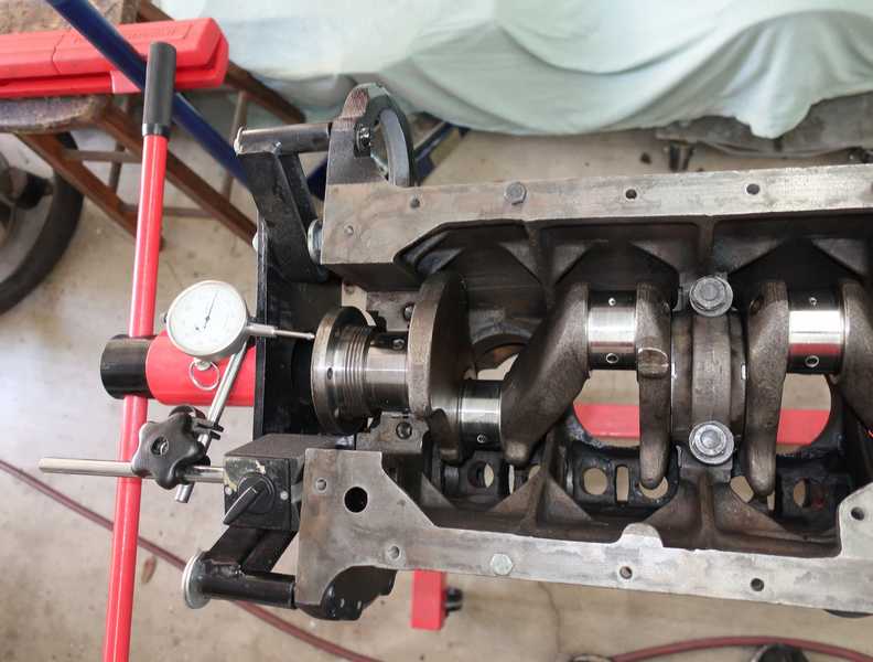
Once the machine work was completed and checked, the engine could be put together. I didn't anticipate any problems, as I had measured all the remachined parts, and they looked good.
I started by test-fitting the connecting rods and checking the bearing clearances with Plastigage. It indicated that the clearances were around 1.5 mils, good values. Because the rods and crankshaft had been completely remachined, there was no need to keep the rods in their original locations. Indeed, I found that I could optimize the clearances by switching them around a bit.
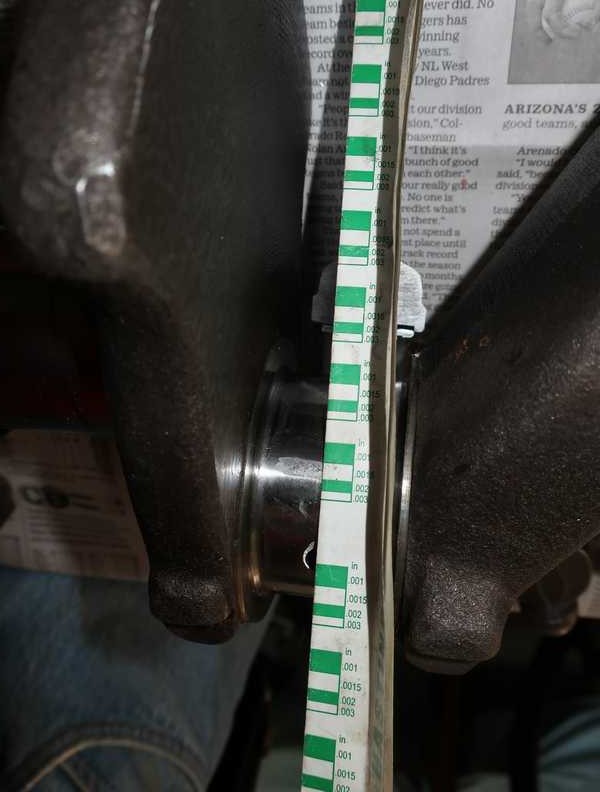
Next, I test-fit the crank, again using Plastigage to check clearances. Like the rods, they were comfortably within spec.
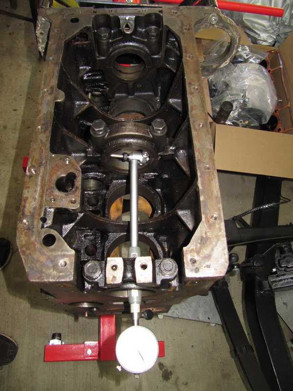
I checked the crankshaft end float with just the center bearing and thrust washers in place. It came out to 5 mils; it has an odd spec, in which 4-6 mils is "desirable," but it implies that significantly greater float is acceptable. In any case, it's right in the middle of that "desirable" range, so I guess I met some manual-writer's desires.
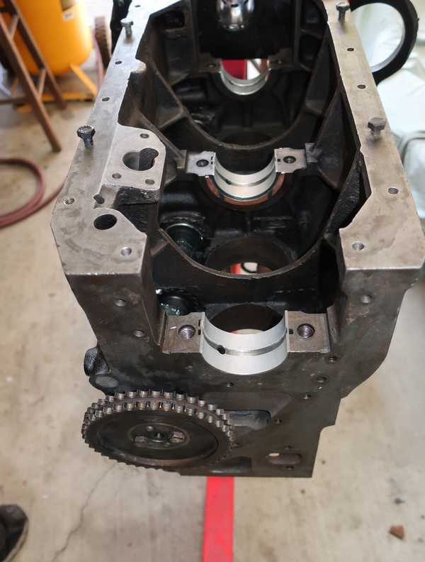
Camshaft and Bearing Installation
Installing the camshaft bearings is tricky. Unlike the rod and main bearings, it's extraordinarily easy to install the cam bearings in the wrong positions; each bearing has several possible orientations, but only one is correct. If a bearing is not installed correctly, the camshaft won't receive proper lubrication, and the bearing will wear quickly.
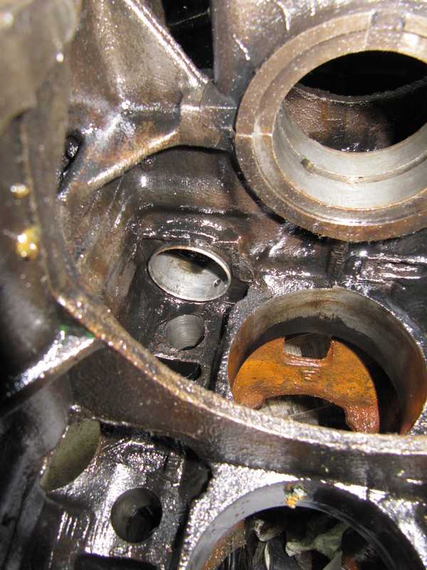
Adding to the confusion, the no. 2 and 4 bearings (numbered from the front of the block) are identical, but the oil holes in the block are not. In the no. 2 bearing, one hole is not used. The picture below shows that bearing as I disassembled the engine; the unused oil hole is visible at the bottom right.
Unfortunately, the shop manual is not much help in this regard. It merely says that it's important that the oil holes line up. (Thanks, guys!) So, here are some things I figured out:
- Bearings 2 and 4 are the wide ones; bearing 3 is the narrow one.
- Each bearing has a large hole that is slightly oval. That hole is for the setscrew.
- Bearings 2 and 4 have a large, round hole, which is an oil hole. It is functional only in bearing 4.
- Each bearing has one small hole. In bearings 2 and 4, that hole lines up with the oil passage to the main bearing. In bearing 3 (the narrow one), there is only one oil hole, so its alignment is obvious.
- In bearings 2 and 4, both the small and large oil holes are offset from the center. That offset should go toward the front of the engine. The oil hole in bearing 3 is centered.
- The washer under the head of the setscrew must be 1/16 inch thick. If it is too thin, the end of the setscrew might contact the camshaft journal, scoring it; if too thick, it may not reach the bearing and won't be effective.
I haven't yet mentioned bearing 1, which is the large, permanent piece at the front of the block. It has one oil hole, but it fits only one way, so it's impossible to install it wrong.
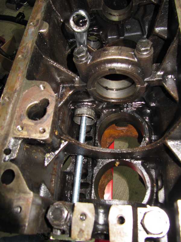
I modified my homemade bearing puller so it could be used to install the bearings; I machined a small recess in one side, so the round piece could slide partway into the bearing and hold it square to the threaded rod. Aligning the bearings for installation is tricky, as the oil holes in the bearings must line up with those in the block. To insure correct installation, I sighted through the bearing bores and made marks on the block, with a felt-tipped pen, to locate the holes. I then lined these up with marks on the bearings before pulling them into place.
The first bearing took a couple tries, but subsequent bearings went into place easily. Below, as an example, the installation of the center bearing. The marks, indicated by the arrow, are a little hard to see. There is another set of marks on the far side of the bearing, but it was impossible to photograph clearly.
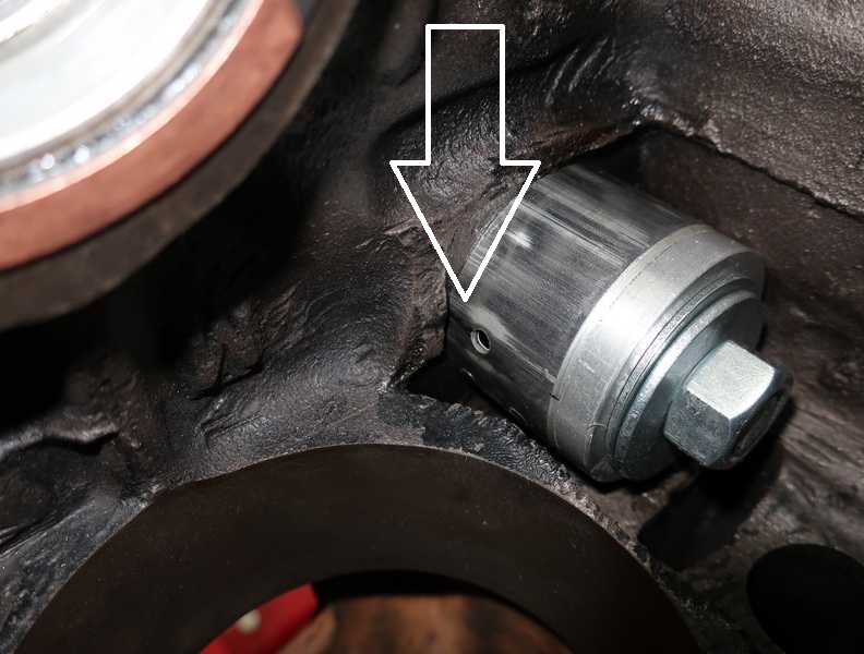
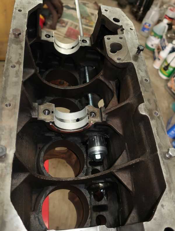
Below, the bearing is almost all the way in. The wrench locks the nut so it doesn't rotate. Another nut, turned by the wrench at the far end of the block in the last picture, pulls the bearing into the bore. To make sure they were correctly inserted, I simply looked through the set-screw holes in the block.
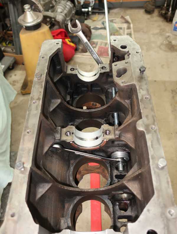
I had to reorient the engine on its stand to do the rearmost bearing. What a pain!
I went to the trouble of aligning the setscrew holes precisely because that's the way the engine was designed. If I had trouble doing that, I would have ground the ends off the setscrews, used them as hole plugs, and trusted the bearings to stay in place; the bearings are so tight in their bores that it seems impossible to "spin" one. In that case, however, it would be essential to run a wire through the oil passageways and make sure that the holes in the bearing lined up with them.
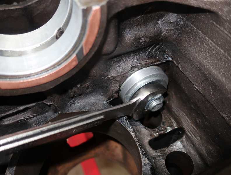
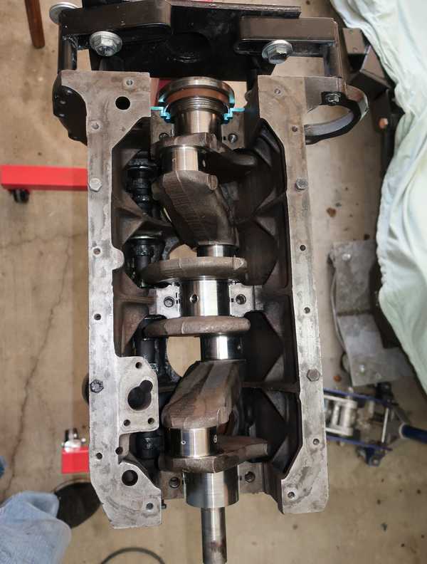
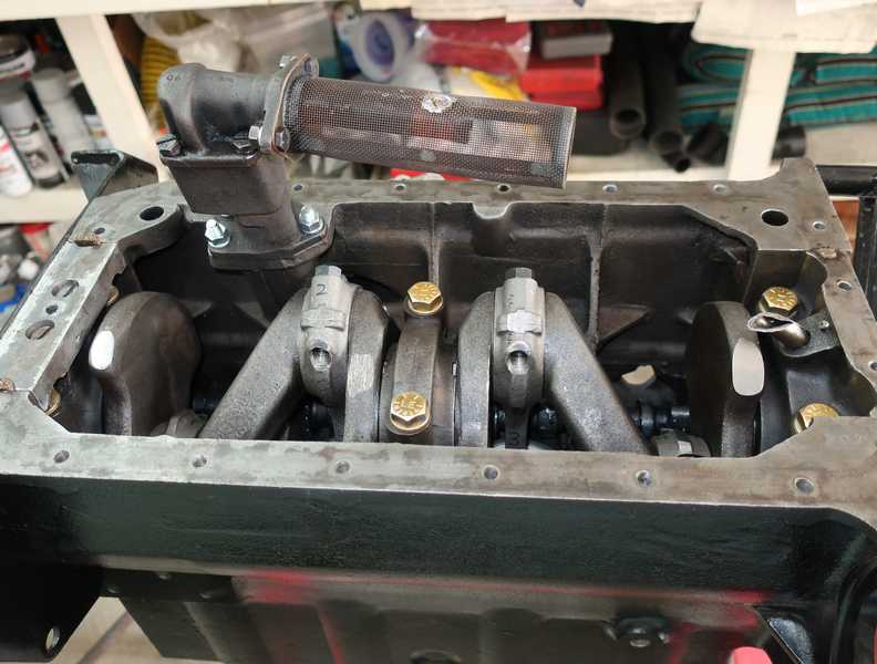
With the bearings in place, I installed the camshaft. I used the old camshaft gear as a handle to turn it, to make sure that it moved smoothly, and to hold it while I wiggled it into position. I dabbed the bearing surfaces and the lobes with a little molybdenum disulfide assembly grease.
The rear plug is important; we really don't want it to leak. I used my standard technique for installing freeze plugs in a block: clean the area with solvent, apply a very small amount of high-temperature sealer (just enough to fill the corners where the plug sits, but not enough to exude into the volume between the plug and camshaft), tap the plug into position (it fits tightly), and dimple the center to make it quite tight in its hole. Even without the sealer, it's unlikely to leak; the sealer just adds a little insurance.
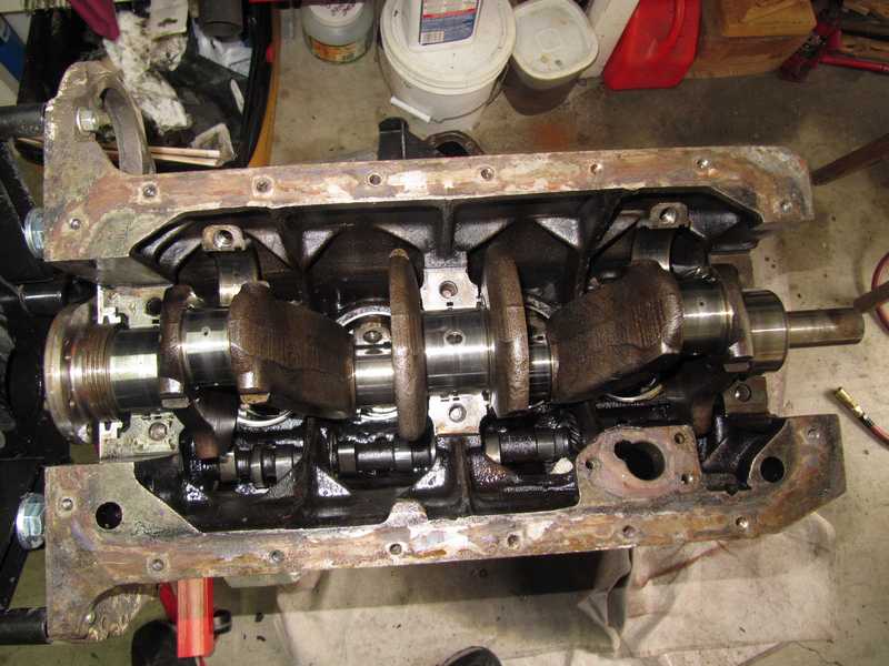
Crankshaft
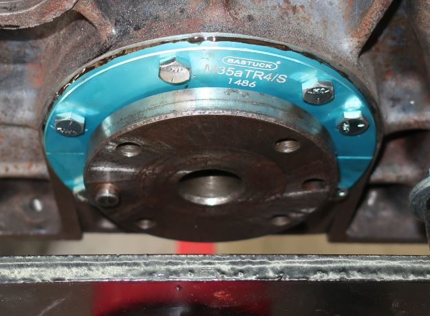
Before the crank could be installed, I had to install my leak-free (ever hopeful!) rear main seal. This is an aftermarket item, which purports to minimize or eliminate leakage around the rear end of the crank. It replaces the original scroll seal, which is not a good design.
Since all the checks had been made earlier, installing the crank and seal was straightforward. The seal housing is aluminum, anodized a pretty blue color. It is aligned with the help of a special tool.
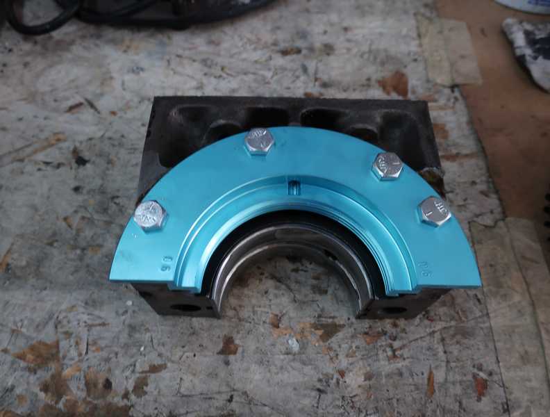
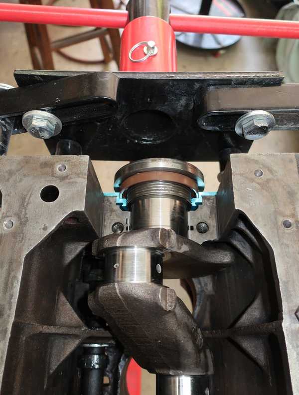
I was concerned that the bolt heads might not clear the flywheel, but I determined that there was indeed adequate clearance. The converse, however, was more of a problem. I later discovered (fortunately, before running the engine) that standard-length flywheel bolts interfere with the seal. It's necessary to shorten the bolts a little, or they will ruin the seal.
After the seal was installed, the bearing caps were torqued, and I had started to install the front plate and timing components, I noticed something I had missed in the seal's installation instructions. It had said, "Position the oil seal so that the join/split [sic] faces upwards." Since the pictures in the instructions showed the engine upside down, as in the above pictures, I naturally took "upwards" to mean "toward the ceiling." Nope. According to a barely legible note on one of the pictures, it meant, "toward the cylinder head." I noticed also that the German section of the multilingual instructions made this point explicitly, while the English section did not.
Must...suppress...urge...to...kill...
So, I took off the rear bearing cap, loosened the rest, and was able to rotate the seal without fully removing the crankshaft. I had to reinstall the felt and cork seals. I'm beginning to doubt that this component was really worth the trouble and expense of installing it. Trying to seal a TR engine completely is probably a fool's errand, and, in any case, a few oil drops never killed anyone.
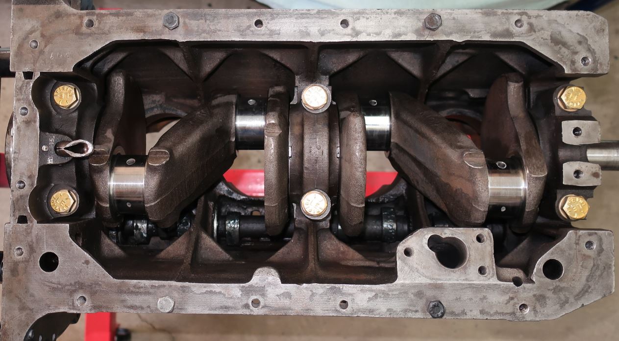
As the original bolts were a little beat up, I installed the bearing caps with new, grade-8 hardware. The thrust bearings were installed with the center cap; you can see the upper halves in some of the pictures at the end of the Camshaft section. For installation of the crank and bearing caps, they are "glued" in place with a little assembly lube.
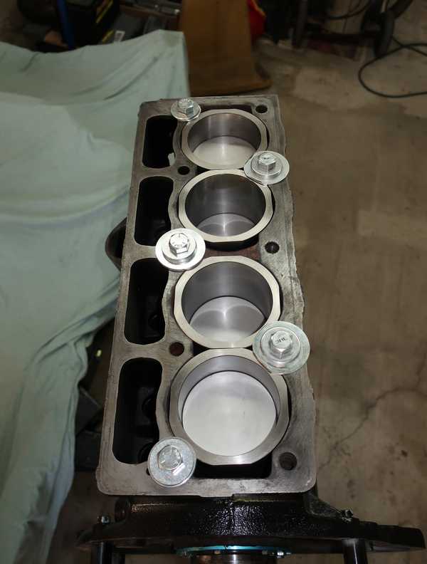
Cylinders
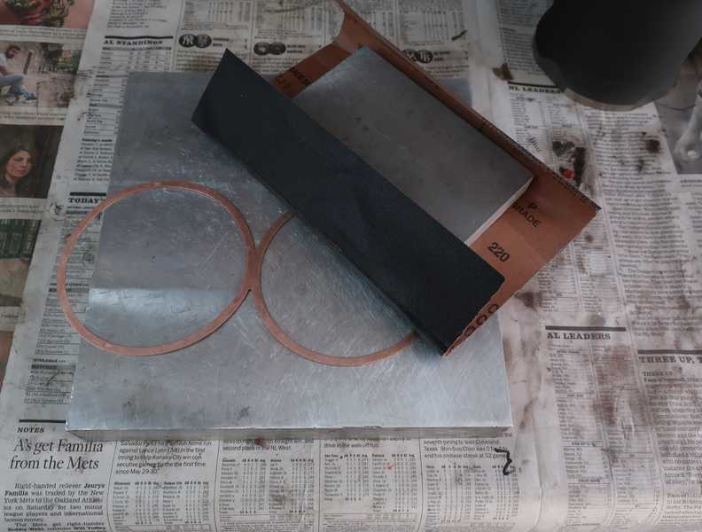
The protrusion of the cylinders above the block surface is critical; the specification is 3 to 5 mils. The protrusion is set by "figure-eight" gaskets that fit between the block and the cylinders. In the past, gaskets of a variety of thicknesses were available; today, the choice is more restricted. A set of 15-mil-thick steel gaskets was included with the piston/cylinder set, and I bought some 20-mil copper ones separately. I had previously determined that the 15-mil gaskets were too thin and the copper ones too thick. Since no other thicknesses were available, I polished the copper ones to about 18 mils by setting the gasket on an aluminum slab and using another big chunk of aluminum, wrapped with 220-grit paper, as a sanding block. The process was slow and tedious, but it did keep the gasket thickness uniform. I checked the gasket thickness repeatedly and test-fit the cylinders several times.
Polishing the gasket revealed that it was not very flat; it had a couple mils of "ripple" along its circumference. This was part of the reason why the protrusion measured earlier was too great. By sanding the gasket, I was able to remove not only this ripple, but the remaining burr along its edges. The measured protrusion then came much closer to what my measurements indicated.
18-mil gaskets should give 4 mils protrusion, plus or minus a couple mils for tolerances, centered in the 3-5 mil spec. I was able to minimize the effect of differences between cylinders by putting the longer ones in the deeper cylinders. Also, the polishing reduced the irregularities in the gasket thickness, resulting in protrusion closer to what I had calculated from individual measurements.
Below right, a pair of cylinders have been installed into the block temporarily, with their gasket, to check their protrusion. Most of them were about 4-5 mils, with an occasional point around 6 mils. That should be close enough.
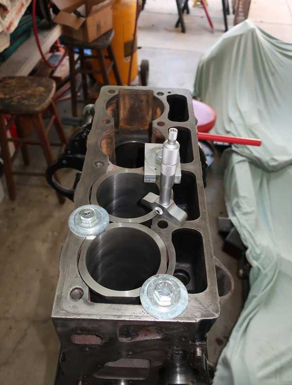
I installed the cylinders and gaskets with Permatex Aviation no. 3 sealer, clamped the cylinders tight against the gaskets, and remeasured the protrusion. I had been worried that the sealer might increase the protrusion, but it didn't, to any measurable degree. That was a good indication that everything was squashed correctly into place. The hold-down bolts in the pictures stayed in place until I was ready to insert the head studs and install the cylinder head.
Pistons
I assembled the pistons and connecting rods. The rods in the pictures below still have their old bolts, which, of course, were replaced.
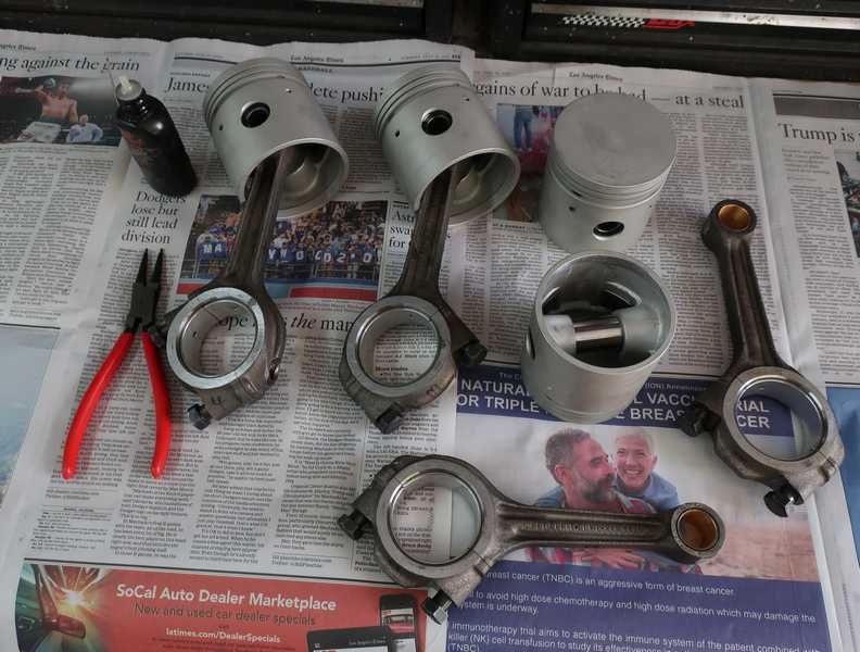
The wrist pins are located by snap rings. It seems unnecessary to note that one should check carefully that they are well seated in their grooves, but people miss this often. The snap ring then comes loose and gets wedged between the piston and cylinder, ruining both.
As with the crankshaft, I checked all the oil passages in the pistons. Between my earlier work and cleaning by the machine shop, they were pretty clean. A good indicator is the tiny oil hole in the center of the crank--in all the pistons, it was completely clear.
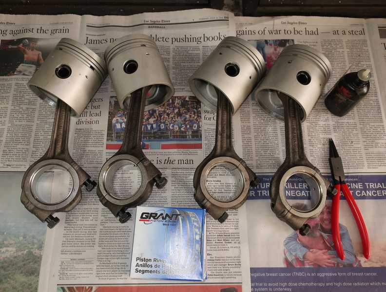
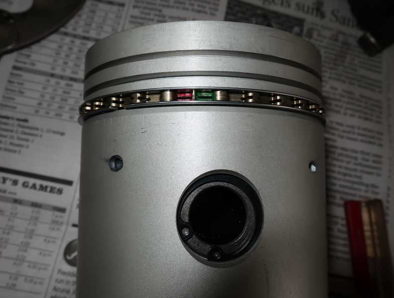
Installing piston rings involves quite a bit more than just clipping them into place. First to be installed is the oil control ring. In the set I received, the ring had red and green markings to show whether the ends of the corrugated piece overlap. If you see both red and green after the ring and its keepers are installed, all is good. But, be careful--blink once, and those &$#!* ends will slip and overlap!
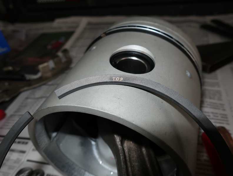
The upper two rings are different and must be installed in their correct grooves. In my set, both had a top and bottom side; the sides were clearly marked. Originally, the top ring had no special orientation, and that is still the case in some sets.
Before installing the rings, it is normally necessary to check the end gap. After installing the rings, the remaining space in the ring groove must be measured. There are specs for these: 10-15 mils for the gap and 1-3 mils for the groove. Since these are new rings and a matched piston/cylinder set, they really should not need attention. I checked them anyway, and, indeed, they were within spec, right out of the box. Finally, the ring gaps must be moved so they are as far from each other as possible.
End-gap specs are a little tricky. The minimum gap is probably the most important spec; if the gap is too small, the ends can meet as the engine heats up, causing the ring to distort and even break. If the gap is too large, the ring can leak a little more than intended, but unless the gap is well out of spec, it probably won't affect compression or blowby noticeably. Some rings are fabricated to size, and it is not expected that the installer will have to modify them. In that case, if the cylinder is a few mils oversize, perhaps from wear, the gap increases three mils for each mil increase in cylinder diameter, and it's expected that the ring might be a little out of spec. Other rings, sometimes called "file to fit," are intentionally fabricated oversize, and the user must file the ends to put them within spec.
I have never seen a set of used pistons that met the groove-width specifications. This point should be considered by anyone planning to re-ring a set of pistons without any further work. If the groove is too wide, the ring gets hammered back and forth in the groove, and it eventually breaks.
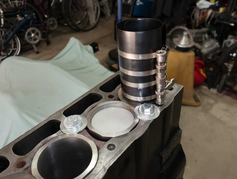
To install the pistons, it is necessary to compress the rings. I used a ring compressor that I'm not happy with, mainly because it's a piece of crap. I've never bought a better one, as I don't use one often, and I can make this one work. Once the compressor was installed on the piston, I wiggled it out just enough to see the ends of the oil-control ring and make sure that they hadn't slipped. To prevent the connecting rod from scratching the cylinder, its end was wrapped with masking tape.
For successful installation, the ring compressor must be flat against the cylinder, with no gap at all; the cylinder oiled; and the crank turned so its journal is out of the way. Then, with the ring compressor held down firmly, the piston is tapped gently into position with a hammer handle. If this is done right, the piston slips easily into place.
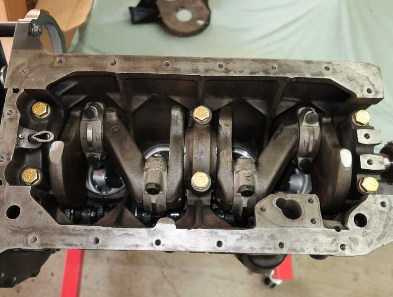
All four pistons have been installed, along with their new cap bolts, properly torqued, and plenty of assembly lube. Even with the pistons in place, the crank can still be turned by hand.
Oil Pump
The oil pump was in good condition. I checked the clearances, as specified in the shop manual, and they all were well within spec. I polished the mating surfaces of the cover and body with fine sandpaper so they would fit together closely. The screen had been soft-soldered to the pickup tube for support, but the joint had broken, leaving a hole in the screen. I cleaned the screen with hydrochloric acid, to expose clean brass, and soldered it again.
I have since learned that it's a good idea to thread a couple wires through the screen and around the pick-up tube to prevent the joint from breaking again. If I every have to remove the oil pan, I'll do that.
The pump was installed in the engine. It uses a gasket between the pump and block, for no good reason that I can see.
External Components
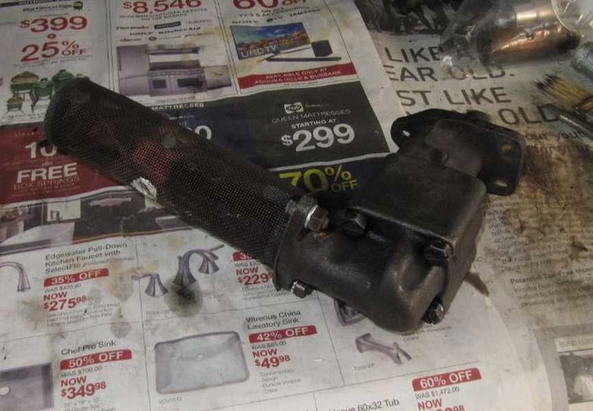
The plugs for the oil gallery were installed, along with the correct copper washers. The cam-bearing setscrews were installed too; they don't use copper washers, even though oil leakage is a possibility, so I used some sealer on the setscrews' threads to prevent leakage. The oil pump drive, distributor drive, and tachometer gear were also installed. The shop manual describes a seemingly odd procedure for setting the distributor-drive end float. This is actually a fairly important adjustment, as the channel that holds the shaft supports the full oil-pump output pressure. If the end float is too great, it can allow too much oil to return to the sump, reducing the oil pressure.
The adapter for the spin-on oil filter was also installed at this point. I still needed to make a blanking plate for the fuel pump, as I planned to use an electric one.
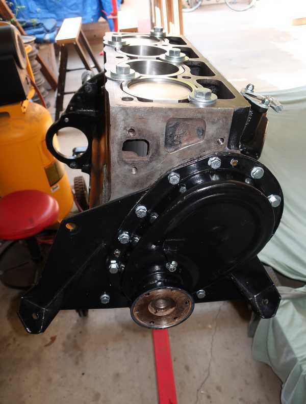
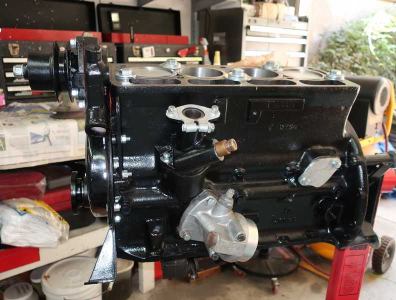
The front plate went on with a gasket. In this picture, some of the bolts were installed temporarily, to compress the gasket while the gasket sealer set up. They were removed for installation of the timing cover.
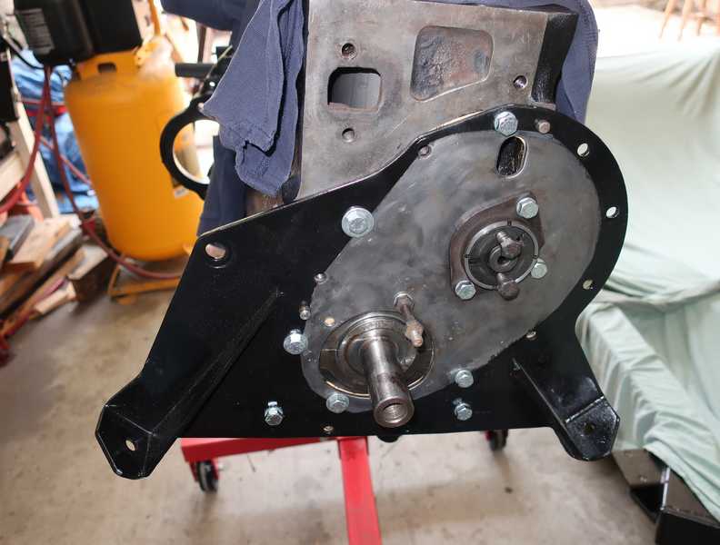
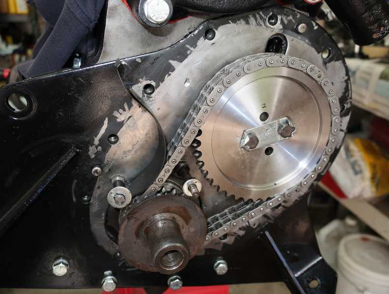
Installing the camshaft and crankshaft sprockets requires a fairly complicated timing effort, described in Valve Timing, a later section. I installed new gears, a new chain, and a new tensioner, as the old ones were worn.
The first step is to make sure that the two sprockets are coplanar. Shims under the crank sprocket are used to adjust this; it's simple but should not be overlooked. The gasket between the plate and the block, supplied in today's kits, is very thin. Because of that, it is possible for the crank sprocket to sit too far forward, even without shims. In that case, it is necessary to fabricate a thicker gasket.
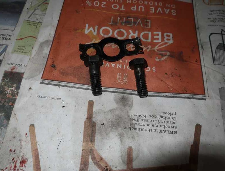
Another important detail concerns the bolts used to secure the camshaft sprocket. They are short, just one inch long, but, unlike most bolts of that length, have a short, unthreaded shank. The shank is designed to be a close fit in the sprocket's threaded holes, and it extends about 1/8 inch into the camshaft (whose threads are a little recessed). I suspect this design is intended to locate the sprocket precisely on the camshaft. It may also provide some support against shear forces, which the shank can support better than bolt threads. Additionally, the bolts require high tightening torque (24-28 lb. ft., fairly high for a 5/16-inch bolt), so they should be grade 8 fasteners. The original bolts were British grade T, which is between SAE grades 5 and 8.
(For what it's worth, the driveshaft's flange bolts have a similar short shank, probably for much the same reasons. So do the bolts attaching the differential ring gear to its "pumpkin." There may be other places, as well, that I can't remember.)
I was not able to find acceptable fasteners, even from the British car-parts suppliers, so I reused the old ones. I would have preferred to use new bolts, but this was the best I could do. If these were not reusable, I probably would have used an ordinary grade 8, 5/16 x 1 UNC fastener.
Here are the installed timing components. I had to make my own locking plate, as new ones were not available at the time I did this work. I think mine's better than the original, anyway; it would be difficult to do worse. (I have since stopped using locking plates here in favor of Nord-Lock washers; see my rant on the subject for the reasons.) I also cleaned the bolts with acetone and flushed the camshaft holes with carburetor cleaner, then blew them out with compressed air. I used blue (nonpermanent) Loctite on the threads, along with Loctite primer, which helps it adhere strongly. I torqued them to 28 lb. ft. before bending the tabs on the plate.
With the crank turned to put the no. 1 piston at top dead center (TDC) on its compression stroke, I adjusted the distributor drive gear and test fit the distributor.
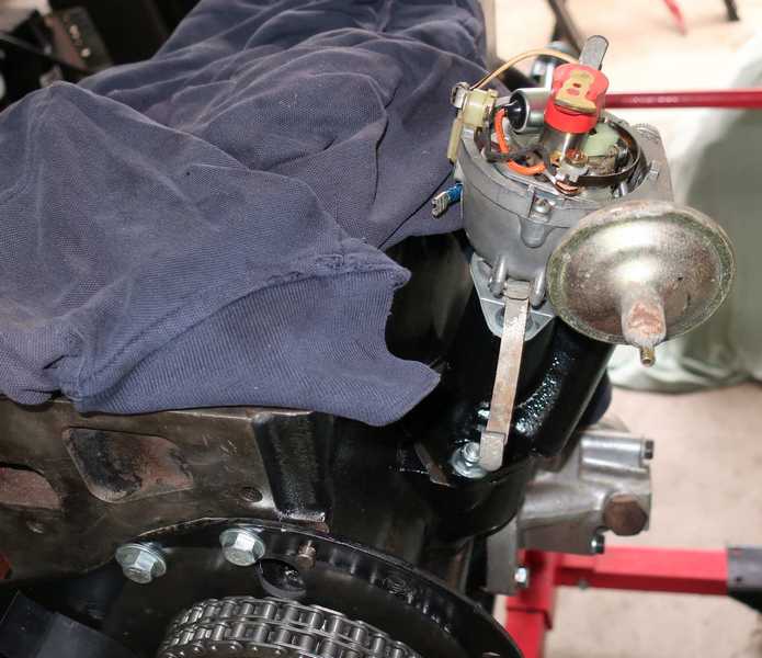
Nothing else to do but install the timing cover, along with a new shaft seal and gasket, of course. I had painted it some time ago and stored it.
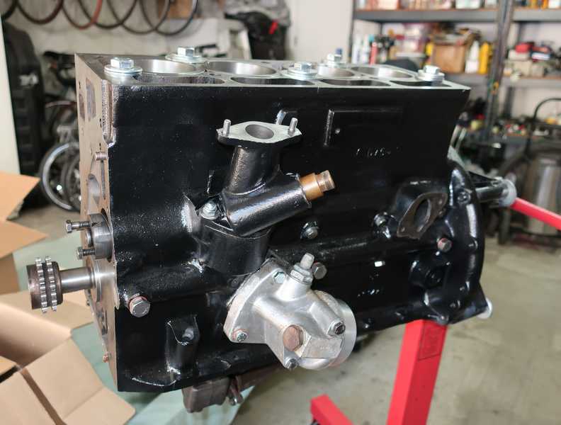
The water pump and generator bracket were installed. I later dabbed a little paint on that unpainted area near the water pump.
I am sick of those stupid little brass valves used to drain the cooling system. They always leak, corrode shut, or both. I replaced it with a bolt and a Delrin washer; the bolt has a steel washer soft soldered to it, creating a kind of flange bolt. When the engine is together, it will be under the exhaust manifold and perhaps a little tricky to access. But a valve would be, too.
Here is the left side, more or less complete. I made a cover for the fuel-pump hole, as I planned to use an electric pump and pressure regulator.
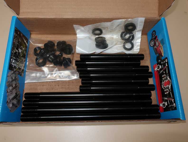
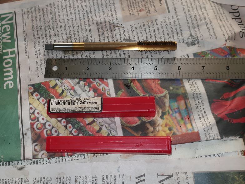
I installed my ARP head studs. Their claimed yield strength of 200,000 PSI greatly exceeds standard grade 8, which is more like 130,000 PSI. Even without the extra strength, they are a beautifully made product and, if you shop around a bit, not much more expensive than standard studs.
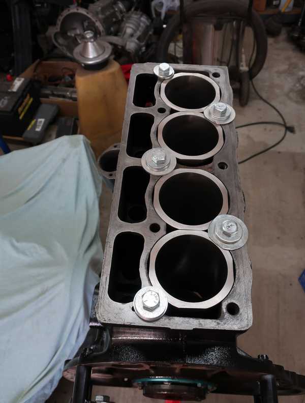
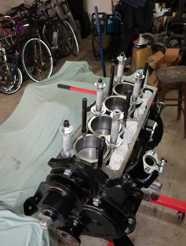
I used pieces of half-inch pipe, 3 1/2 inches long, and some washers to make new hold-downs for the cylinders. The pipe pieces were oily, not particularly clean, and their ends were not very square. I squared them on a lathe and washed them in acetone before installing them. I also installed the new tappets; the clumps of paper towel prevented dirt or wayward bits of hardware from falling onto them. It also prevented them from falling out when I turned the engine over.
The oil pan was installed with a gasket, sealer, and 19 bolts. I hope I never have to remove it.
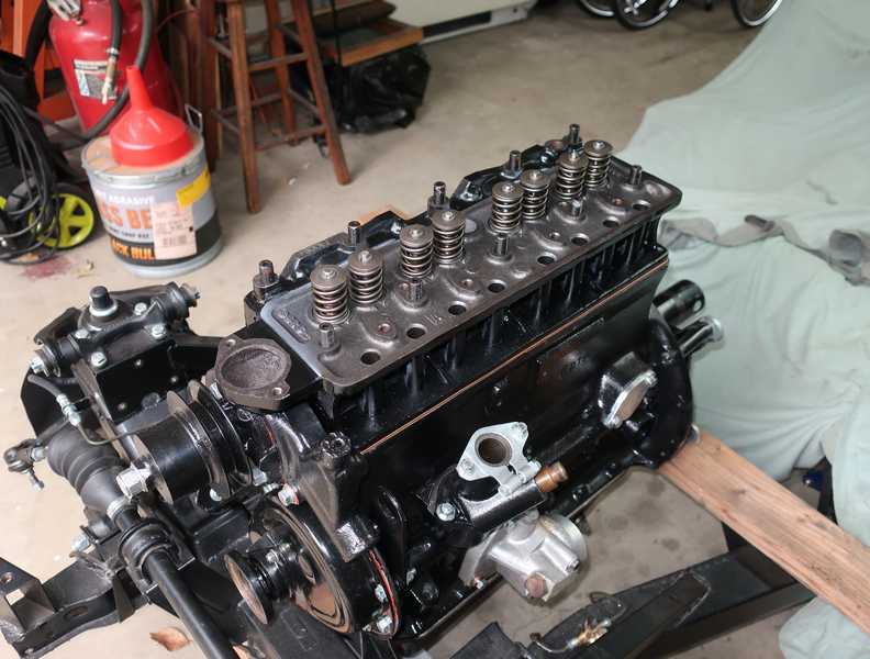
Cylinder Head
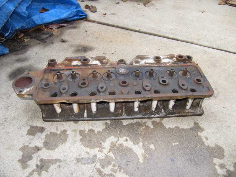
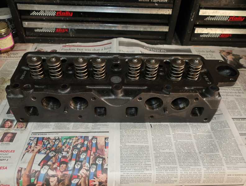
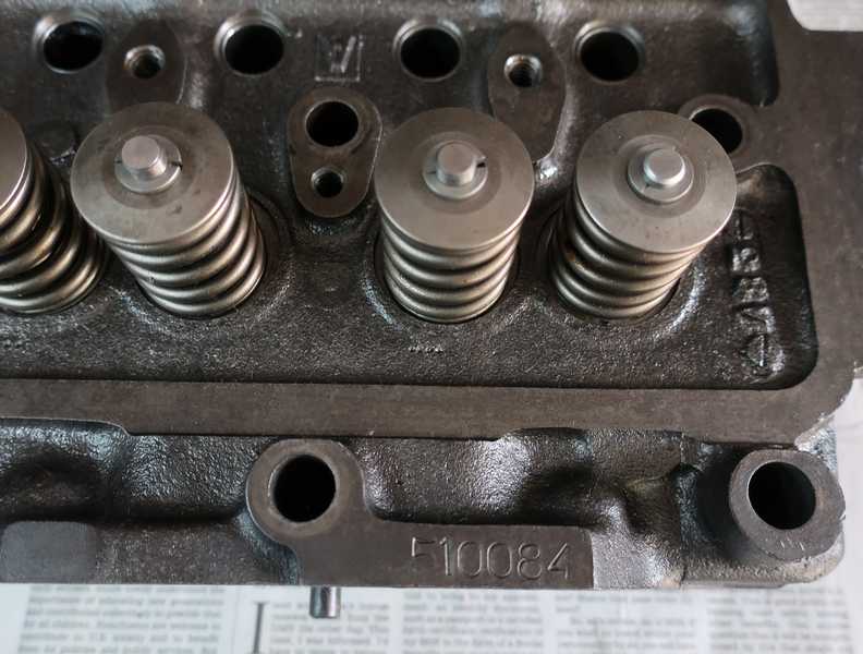
I discovered that I had a cylinder head from a TR4, not a 4A. The TR4 head has the part no. 510084, while most 4A heads have no. 511695. The TR4 exhaust valves also have thicker stems than the intakes, and they have three springs instead of the intakes' two. Beyond that, it's pretty much the same as the 4A. The heads are interchangeable.
I removed the valves and checked them. I found that the valve springs were not assembled right: the intake valves had three springs and the exhaust valves two. It should have been the other way around. The valves' shafts were all close to, or past, their wear limits, and, on several, the heads' contact rings were worn so much they had become cupped. The valve guides were also worn well past their limits. This seemed a good time to do the whole head, with new valves, hardened seats, and the usual flatness and crack checks.
I was musing about seeking out a genuine TR4A head when the obvious descended upon me: I had a spare engine. It had been sitting under a tarp for the past year, largely forgotten. Maybe it had a TR4A head! I checked it and discovered that it was a TR4 engine (no. CT19515E) with a 4A head, part no. 511695! It seemed likely to be the original head, and the heads simply were swapped at some point, perhaps because the 4A head needed work and the TR4 head was usable.
With the valves out and the head washed with strong detergent, it didn't look too bad. Any doubts about its originality disappeared when I saw the remaining paint: it was white, same as the block. (TR4A engines, as they came from the factory, were black, so the white paint on both the block and head shows that they were together when repainted.)
Head Restoration
I sent the head to a specialist machine shop (APT in Riverside, California) and got the bad news that my 4A head was not usable, having multiple cracks. That left me back with the TR4 head. I ferried it out to Riverside and left it with the rebuilder.
Below is the TR4A head; the cracks are marked with yellow ink. They are not as bad as I had expected, and, according to the machinist, the head still could be repaired, at some cost. I'll keep the head; someday it may be worth the cost and trouble of fixing it.
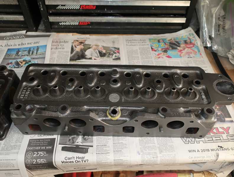
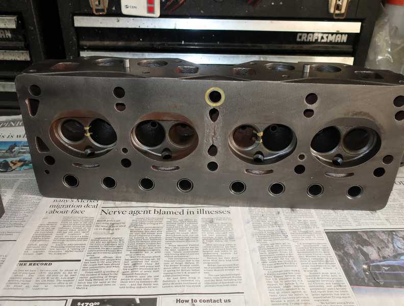
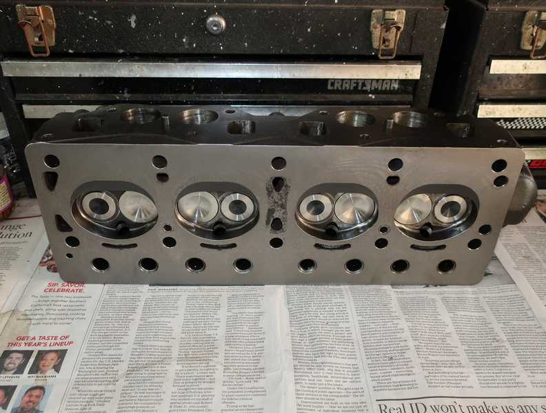
The completed head is (arguably) no longer a TR4 head, given its modifications. It has bronze valve guides sized to allow the use of TR4A exhaust valves, which have 5/16-inch stems instead of the TR4's 3/8-inch, and TR4A-style double springs on both the intakes and exhausts. Hardened exhaust seats have been installed, and all seats have a three-angle grind. It's a really nice head now.
The surface was lightly shaved to remove minor irregularities. All parts are new.
I usually don't farm out restoration work that I can do myself, but in this case, I thought it made sense. Obviously, I couldn't do the machine work, but local shops probably could, and I certainly could have assembled the valves and springs. However, I wanted the work done by a British-car specialist, as installing hardened seats has to be done right; if not, a seat could come loose, and I don't want to think about the damage that could do. And, this way, the shop takes responsibility for the whole thing.
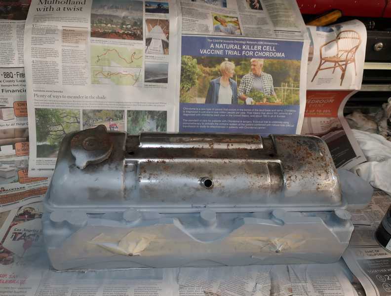
I masked, primed, and painted the head. I used the old spark plugs to fill the spark-plug holes and the old valve cover to mask the valves. I used Duplicolor engine paints, same as for the block.
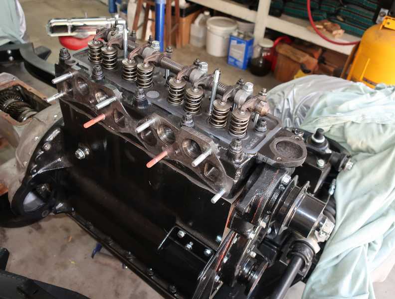
The head is finished and ready for installation.
Cylinder Head Installation
Two mildly controversial matters regarding head gaskets:
- Sealer. The shop manual instructs us to use a sealer on the head gasket. This is a bit unusual, as most head gaskets are not sealed; you just install them dry. The manual provides little guidance as to the type of sealer to use, so there are lots of opinions. I chose to use a copper-based spray sealer, Permatex Copper Spray-A-Gasket, which is specifically intended for head gaskets. Other recommendations are Wellseal (good luck getting it in the US!) or just a light smear of grease (which actually is a factory recommendation for the MG TD).
- Which side goes up? Again, a subject of perpetual discussion. I did a little research and found that the great majority have the side with the folded edges upward. That makes sense to me; orienting it downward has much the same effect as adding the copper thickness (maybe about 10 mils?) to the cylinder protrusion. That said, the gasket I removed from the engine on tear-down had the fold downward; there was no sign of a problem, such as water in the oil or burn marks on the gasket. The compressions were decent, as well. Perhaps it doesn't really matter much.
The instructions for the copper gasket spray don't tell you much. In particular, there is no info on how thick to coat the gasket. I sprayed a few coats so it was good and sticky, but with no obvious build-up. In any case, the first picture below shows the copper-sprayed gasket installed; the second, the head set in place.
Along with the studs, ARP supplies hardened washers, their own thread lubricant, and cool "12-point" nuts, which are tightened with a 9/16-inch, 12-point socket. I torqued the head nuts in four stages: 50, 75, 95, and 110 lb. ft., in the order specified in the manual, of course. The shop manual's spec is 100-105 lb. ft., but ARP recommends 110.
Jobs like this make me glad that I invested in a high-quality (Snap-On) torque wrench a few years ago. I bought it used, but it came with new calibration documentation, so I know it's accurate.
Retorquing the Head
After typically a few hundred miles, it's necessary to retorque the head. There is a lot of controversy about the right way to do it, but I suspect it's most important just to do it, and the method is less important. To do this, I retorqued the head nuts in tightening order, first backing off a flat or so and then bringing them back to the original 110 lb. ft. tightness. I was surprised at how much I had to turn the nuts; it was so much that, on the first nut, I suspected a problem with the torque wrench's calibration. I confirmed it was OK by checking against another torque wrench.
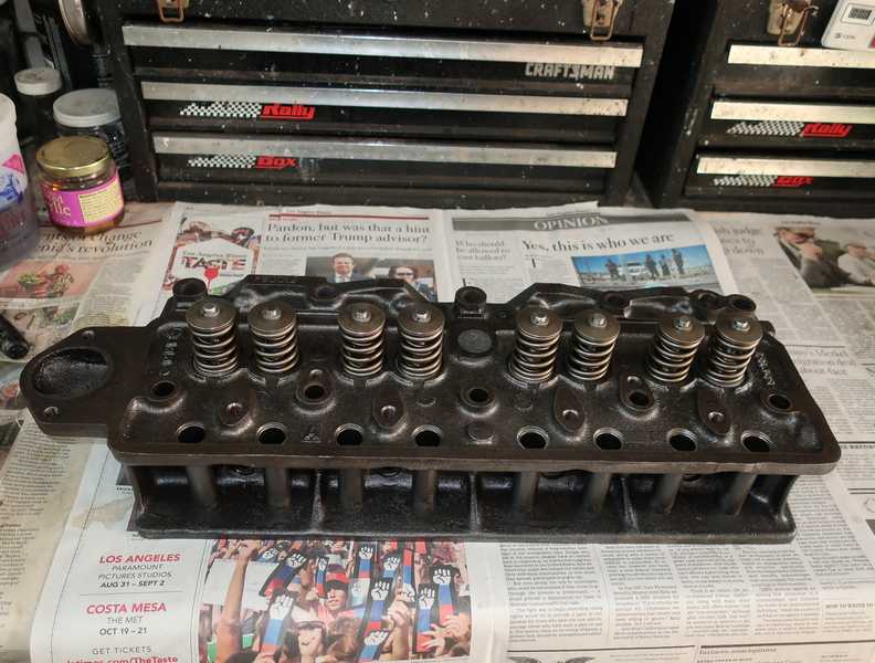
Retorquing the head nuts requires removal of the rocker assembly. To reinstall it, the adjusters must be loosened and one must make sure that the adjuster balls sit correctly in the pushrods. Then, the mounting nuts can be torqued correctly (25 lb. ft.). Readjusting the valves is necessary, of course.
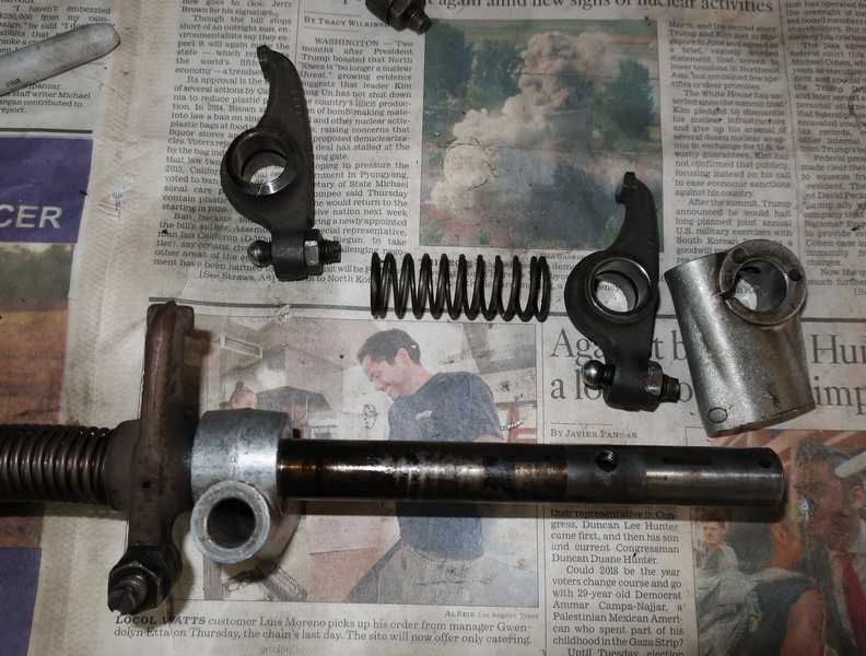
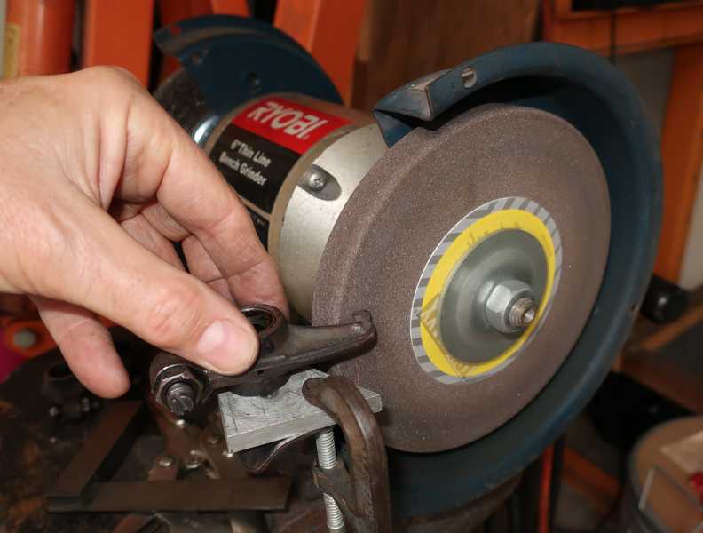
Rockers
The rockers (on the TR4 head) looked better than they actually were; in fact, at first I thought they were almost new. Their adjusters were undamaged, something you see only on new parts, and the contact areas with the valves were not badly worn.
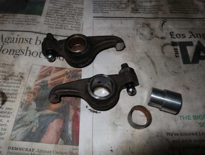
When I slid a rocker to the side, I could see shaft wear, so I decided to take the assembly apart and evaluate it properly. It was, in fact, significantly worn. Not only was the shaft worn, but the rocker bushings showed 5 to 10 mils of wear. Definitely time for a rebuild!
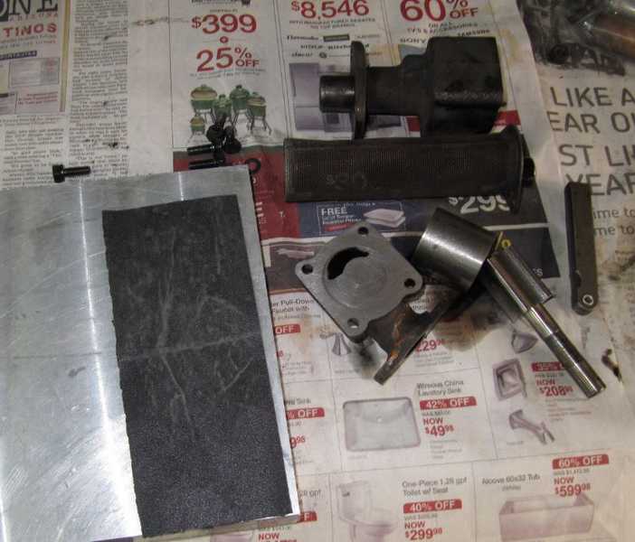
Replacing the bushings is straightforward, but it does require a fair amount of special equipment. The first step is to remove the old bushings; each rocker has two of them. That is most easily done by tapping them out with a pin punch from the inside. The trick to removing them easily involves recognizing that the bushings are split. Placing the punch next to the split and giving it a couple modest whacks pushes out one end; then, the rest of the bushing can be tapped out easily.
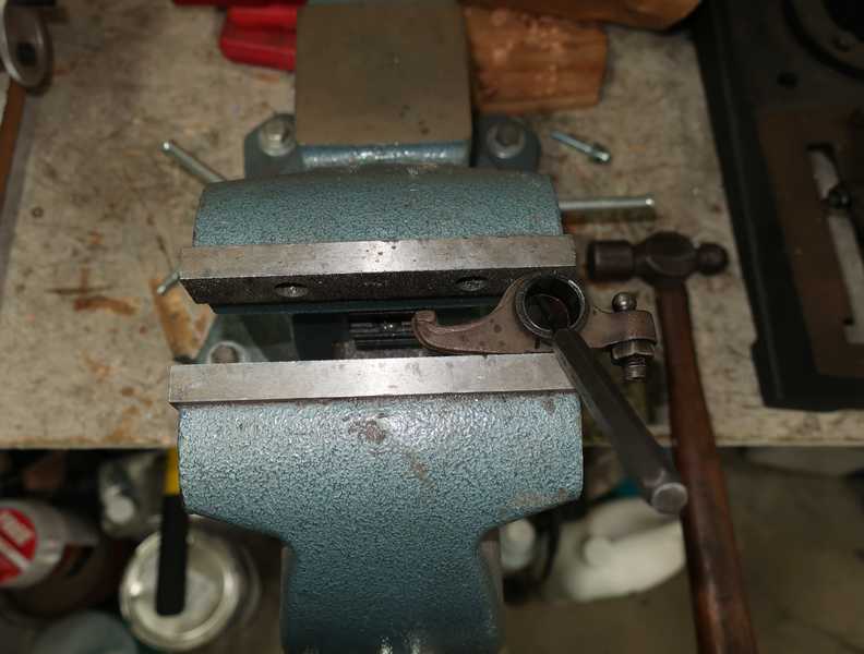
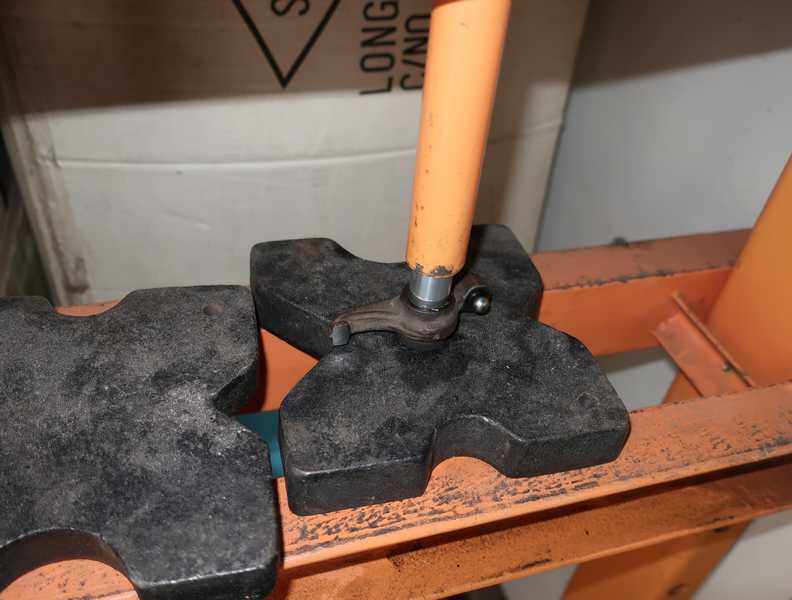
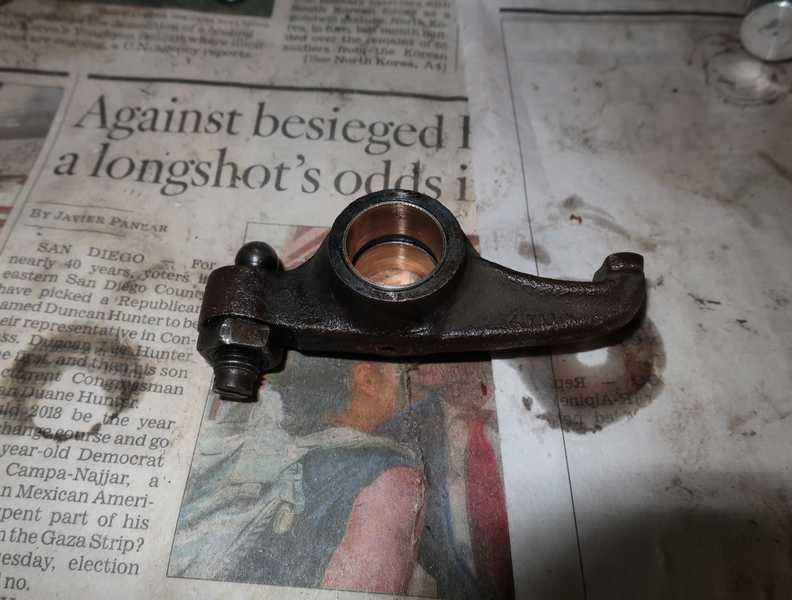
To restore the rocker ends, I clamped a piece of scrap 1/4-inch aluminum to my grinder's rest and made sure that its surface was perpendicular to the side of the wheel. Then, I just held the rocker down and ground its end, moving it slowly back and forth to create a slightly curved surface. It's best to restore the rocker ends before installing new bushings, as any protrusion of the bushing may prevent the rocker from sitting flat against the rest.
I confess to being a little uncertain about this process. Most parts like this are case hardened, meaning that only the outer layer of steel is hardened, not the full thickness. I don't know how deep the hardened layer is, and I'm concerned that I might grind it off; then, the rocker will wear more rapidly. Still, after all, this is a common practice, and in any case I removed no more than 20 mils of steel. I'll keep an eye on the rockers and see what happens.
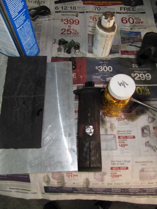
I made an aluminum tool to hold the new bushings straight while I pressed them into the rockers. In the second picture below, you can see the tool, a new bushing, a rocker with its new bushings, and one whose bushings have been removed.
The bushings, as installed, have an inside diameter of 0.600 inches. The diameter of the new rocker shaft is 0.624, so the bushings must be reamed. I could not find a spec for the bushing diameter, but the 0.624 shaft diameter seems intended for a 0.625 diameter rocker (5/8 inch), so I reamed them to that value. In any case, ~1 mil clearance seems right, as the rockers slide smoothly onto the shaft and there is no perceptible wobble.
Reassembling the rocker shaft assembly was mostly straightforward. The supports have to be pressed onto the shaft, and there is nothing in the assembly that helps to locate and align them correctly. The supports are located between pairs of the rockers' oil cutouts; I found that I could "eyeball" the spacing fairly accurately. I did encounter one problem: the cap at the front end of the assembly compressed the adjacent spring completely and locked the forwardmost rocker; there just wasn't enough room. I put the cap in my lathe, took 20 mils off the end, and then it fit well. Yet again, the kind of imperfection common with new parts.
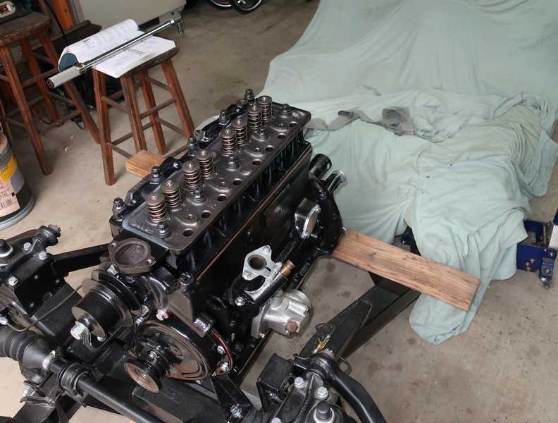
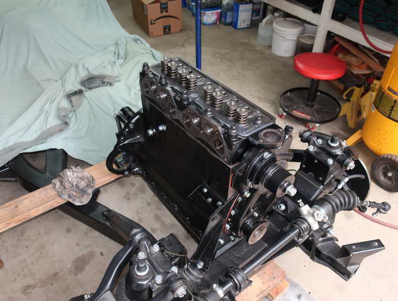
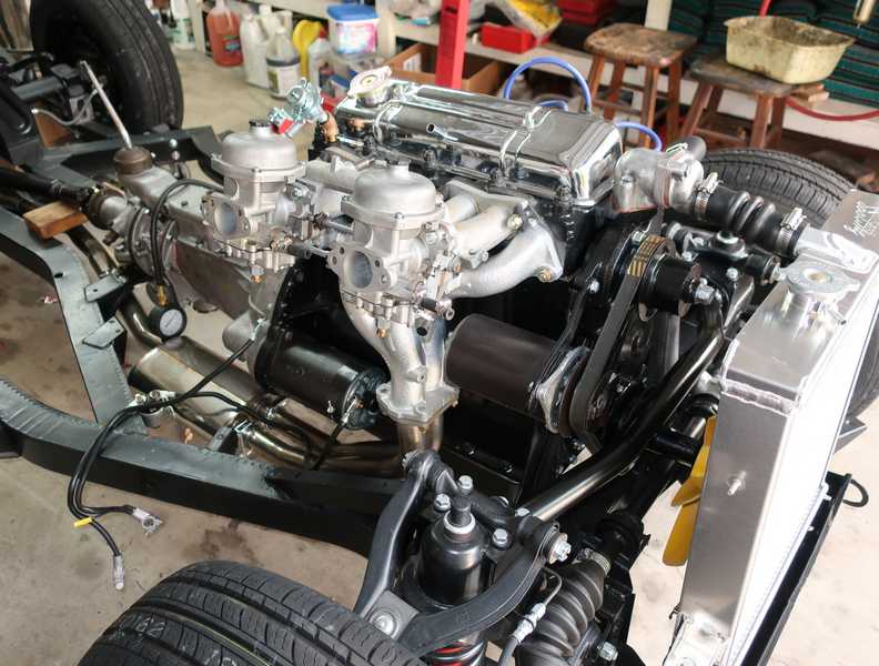
Finished Engine
A couple pictures of the finished engine, mounted in the chassis, to complete the page.
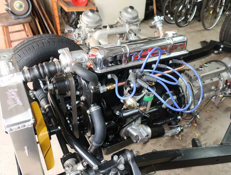
At this point, I tested the engine. It started and ran for 20 minutes with good oil pressure and no apparent problems.
Once the car was back on the road, I was more than a little pleased at how well the engine ran. I can only hope it stays that way!
Valve Timing
Theory
Setting the valve timing, on most engines, is simple. You just install the timing gears and chain (or belt, in most modern cars) so that a pair of markers line up. Could it be that simple on the TR engine? Of course not.
Triumph gives us the opportunity to get the valve timing precisely correct (or, if you're as cynical as I am, the opportunity to screw it up royally). The mounting holes in the camshaft sprocket are offset in such a way that you can change the timing in increments of one quarter of the distance between adjacent teeth. That is done by selecting the set of mounting holes and the side of the sprocket that faces outward. Two sets of holes, two sides of the sprocket; that's four options.
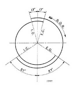
To align the camshaft, it must be set precisely at the point where the no. 1 cylinder's intake and exhaust valves are equally open, as the exhaust valve is closing and the intake is opening. In a completed engine, this corresponds to top dead center (TDC) on the exhaust stroke. The crank is then set so the no. 1 piston is at TDC, and the camshaft sprocket is installed in the position that allows the chain to fit correctly. The cam lobe positions, as viewed from the front of the engine, are shown below. The figure is from the shop manual.
The method for doing this, described in the shop manual, is clumsy and inaccurate, and it requires that the engine be fully assembled. Better methods exist. The best method I have encountered involves setting up the camshaft and the crank separately. Setting the camshaft position involves a substitute tappet, whose height can be measured with a dial micrometer. (Some people use an ordinary tappet and a pushrod, but I found it difficult to obtain consistent micrometer readings that way; if the cylinder head is in place, though, that's your only option.) With a degree wheel on the camshaft, the positions of the camshaft are found at which the tappets for the intake and exhaust have some given height above their lowest positions; something like 0.100 inches is fine, but for best accuracy, it's good to check several points. The correct camshaft position is halfway between those two positions.
Finding TDC of the crankshaft is simple, in concept; you just put a micrometer on the piston and rotate the crankshaft until you're there. However, it can be difficult to determine TDC precisely in this manner. It's better to do something similar to what's done with the camshaft: find a defined position on either side of TDC, with a dial micrometer and degree wheel, and then TDC is halfway between those two points.
Once this is done, the timing should be as shown in the shop-manual figure below. The intake valve begins to open 17 degrees before TDC, and the exhaust closes 17 degrees after TDC. As 1/4 tooth spacing of the cam sprocket corresponds to 4.3 degrees of crankshaft revolution, which is easy to resolve with a degree wheel, it should not be difficult to check the timing and determine that it is correct.
A Note on TDC
The position of the crankshaft for this procedure is TDC of the exhaust stroke. When a distributor is set up, the crankshaft must be at TDC for the compression stroke. Thus, if a new engine is being timed, the crank must be rotated a full turn, establishing TDC of the compression stroke, after the camshaft timing is completed, before the distributor is installed.
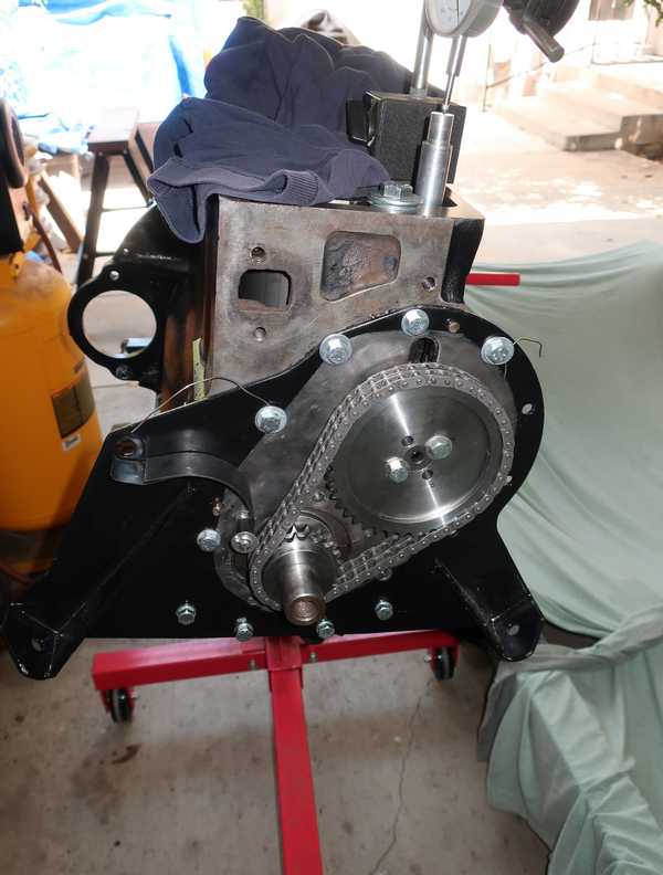
Camshaft Setup
The setup for the camshaft is shown below. The substitute tappet was machined from a piece of one-inch aluminum round stock. Many people use an ordinary tappet and pushrod, but the accuracy of that arrangement is suspect, as the pushrod can move around a lot, affecting the measurement. The degree wheel was downloaded from the Internet, printed, and glued to a piece of thin plywood. A piece of stainless steel wire, bolted to the engine mounting plate, served as a pointer.
I determined the positions of the intake and exhaust for three values of tappet height, 0.100, 0.150, and 0.200 inches above their minima. So, for example, I noted the positions of the degree wheel when the exhaust was 0.100 about the minimum, while decreasing, and when the intake was 0.100 above the minimum, while increasing. The point on the degree wheel halfway between those values was the desired camshaft position. With three sets of heights, I had three values of the halfway point, which I could compare to make sure that I had found the camshaft position accurately. Fortunately, they all matched within a fraction of one degree.
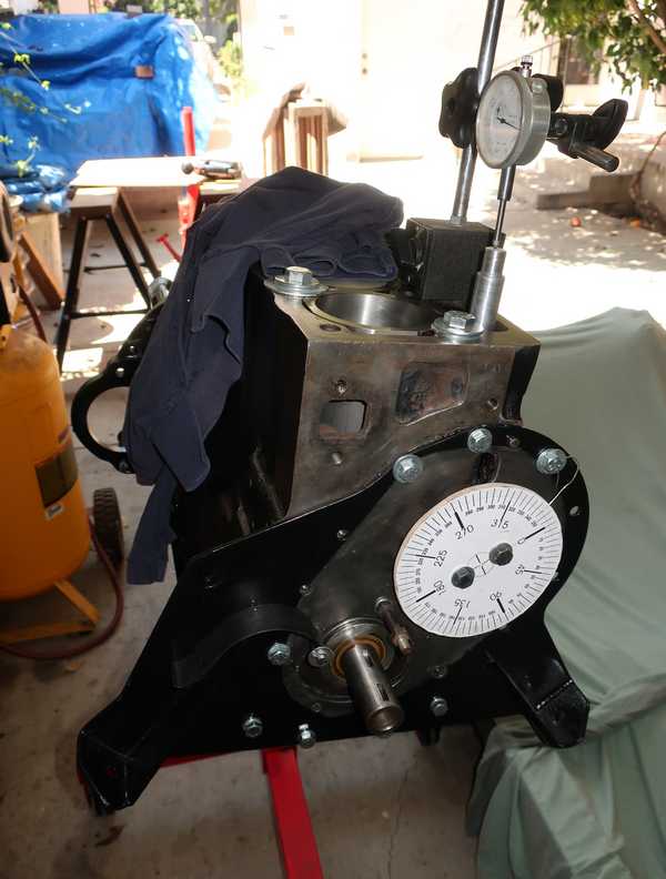
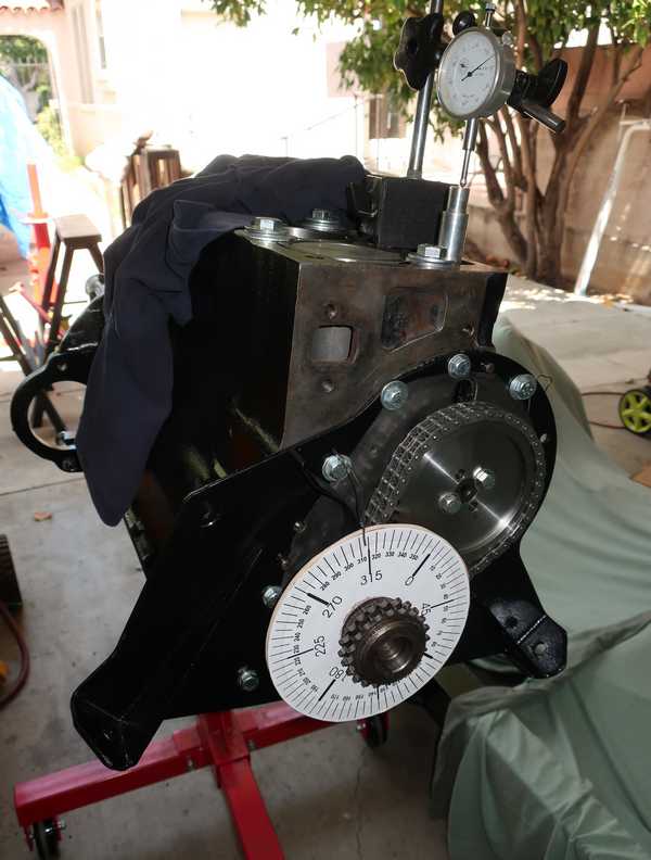
Next was the crank. I used a larger degree wheel, glued to the back of the old crankshaft sprocket. (Naturally, the dial micrometer should be on the piston, not the substitute tappet; when I took the picture, I just hadn't yet moved it.) The goal of this step was to find TDC accurately. The obvious way, which would not require a degree wheel, would be to move the crank until the piston reached the top, as indicated by the dial gauge. That wouldn't be very accurate, though, because the vertical motion, per degree of crank rotation, reaches zero at that point. A better method is to note the crank positions at two points the same distance from TDC, as indicated by the micrometer, but on different sides of the TDC point. Then, TDC is simply halfway between those points. For best accuracy, it's wise to find both points while moving the crank in the same direction. That direction should be the normal direction of revolution, which is clockwise.
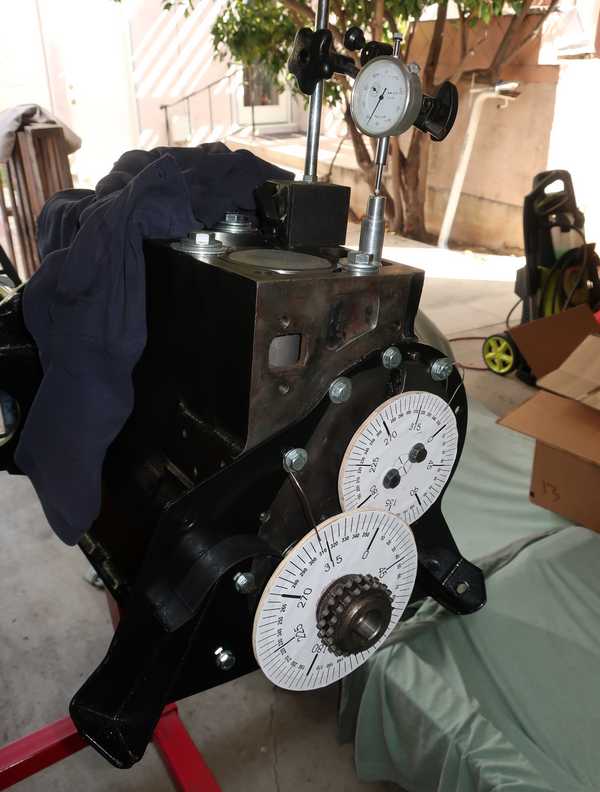
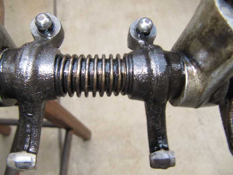
I marked the points on the camshaft sprocket corresponding to quarter-tooth increments. I did this by clamping two 5/16-inch bolts in a vise, sliding the sprocket onto them, and noting the positions of the teeth. Position 1 is the zero point, position 2 (on the opposite side of the sprocket) is 1/4 tooth, position 3 is a half tooth, and 4 (also opposite side) is 3/4. The arrow shows how the tooth position moves with each increment. This way, I just line up the chain, note how many increments I have to move the sprocket in the marked direction for it to fit, and select the right position. Simple.
One important point: the engine turns clockwise, as you face it from the front. Since the chain has a little slack, the tooth-alignment check must be made on the taut side of the chain, which is the lower right side (again, as you face it). For the same reason, the chain must be held quite taut when the check is made. This is a critical adjustment.
Removing the sprocket, which fit tightly, inevitably moved the camshaft. I kept a micrometer on the substitute tappet so I could reset it to the precise position. I had determined earlier that 2 degrees of camshaft rotation, approximately one 1/4-tooth increment, changed the tappet height by 12 mils. That's sensitive enough to be sure that the cam, once moved, is reset to the original position.
I bought the slightly-more-expensive AE timing chain. It's a nicely made part, much better than many I've encountered. It has a removable link to facilitate installation (upper center of the picture). Its installation instructions are important, as they contain information that is not in the shop manual.
I lined up the chain and determined that I needed to move the sprocket by 3/4 of a tooth increment. I removed the sprocket, flipped it, and selected the appropriate set of mounting holes. After reinstalling the camshaft sprocket, the chain lined up perfectly.
At this point, I still needed to add the tabbed locking plate for the camshaft sprocket. The plates were not available at the time I was working on the engine, so I had to make my own. (I have subsequently developed a lot of skepticism for locking plates; see my rant elsewhere. I now use Nord-lock washers and thread locker for this application.)
To be sure I did everything right, I checked the timing. I measured the crank positions for a specific intake and exhaust tappet height above the minimum (I used 25 mils). Because of slack in the chain, these points must be approached while turning the crank and camshaft clockwise, the normal direction of the engine. If the chain is adjusted right, these points will be equally spaced either side of TDC; the actual value is not important. I measured precisely 7 degrees for both, so I was confident that the chain was installed correctly and the timing was right.
Before installing the timing cover, I oiled the chain, so it wouldn't be dry at first start-up.