![]()
Differential Overhaul
I hate differentials. To rebuild one, you need special tooling, which is usually not available and wildly expensive when it is, and the procedures in the shop manuals are invariably complicated and incomprehensible. Nevertheless, I've managed to repair or rebuild a couple of differentials. It requires an understanding of what needs to be done, which is actually pretty simple, and sometimes a bit of creativity to circumvent the need for special tooling. The actual business of setting one up, however, can be a lot of work. Because it's a fairly long story, I decided to describe the overhaul of the differential in this separate page.
I didn't get the differential right first try. I had to remove the rear axle and redo it after the car was completed; as you might imagine, my experience did not inspire any new love for the little bastards. Setting it up was tedious in the extreme, and, insult to injury, I had to do it twice. In the end, I determined that the used set of gears I obtained probably was too worn, and for the second try, I bought a new gear set.
Click on any picture to see a larger version in a new window.
Contents
- Resources
- Initial Inspection
- Technical Notes on the TR Differential
- Tools
- Disassembly
- Reassembly and Setup
- Second Try
- Part Numbers and Dimensions
Resources
It's no great surprise that the web doesn't have much on TR differential overhaul, since few of us are benighted enough to take on that job. Nevertheless, I found a couple useful web pages:
Differential, Rear Axles, and Driveshaft: This is a PDF scan of an (apparently) rather old, printed document. It's hosted various places around the net, but it doesn't appear to have a primary home. There is useful information in this document, but the author's measurement procedures are not terribly accurate. They should be good enough for a start, however, followed by fine tuning with gear-marking compound.
Here and here are a couple of good YouTube videos explaining ring-gear setup. There are more; do a search.
TR6 Pages: A good description, but not very clear on how the pinion depth was determined. The author seems to depend largely on the previous document, although his measurement technique is better.
Even though it specifies the use of tools that you and I will never see, the TR4/4A shop manual is also an essential reference.
Like the other pages of my TR4A site, this page is intended to be documentation of my work, not a tutorial. For the latter, consult the above references, a knowledgeable expert, and, especially, a shop manual.
Initial Inspection
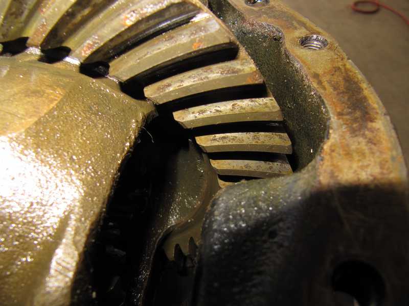
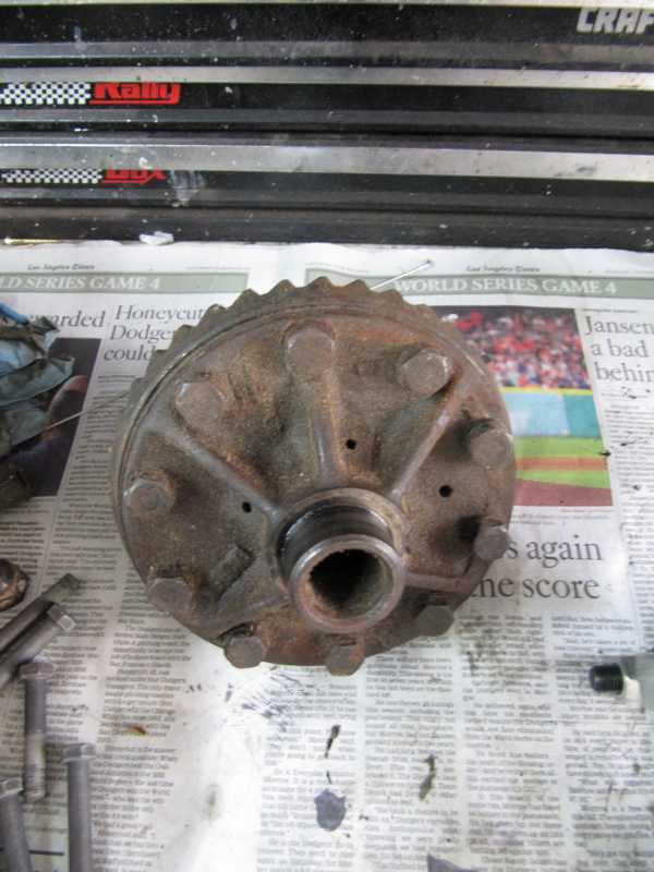
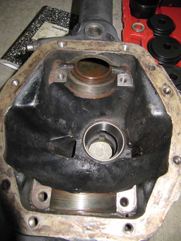
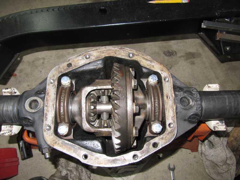
When I opened the TR4A's differential, I expected a quart of stinky gear oil to pour out. Instead, I got a dribble of about a quarter cup of oxidized oil. The oil clearly hadn't been checked or replaced for many years, if not decades. That's not good for a set of gears and bearings, and the ones in this differential paid the price.
Although the differential was not loose in the housing and the backlash, while out of spec, wasn't too bad, I thought there was a very good chance that the bearings were worn or corroded. (The differential must be disassembled to inspect them.) Worse, the ring gear had areas of disturbingly bad corrosion. It was clear that the differential would have to be overhauled completely.
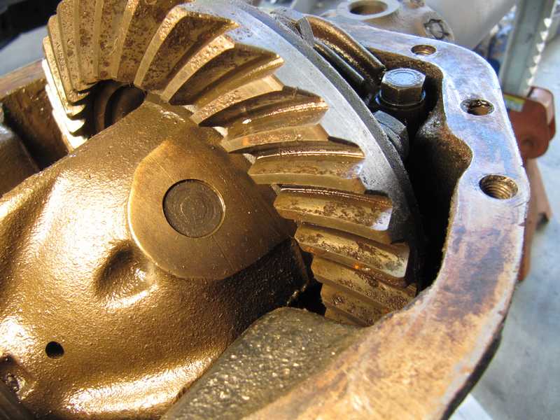
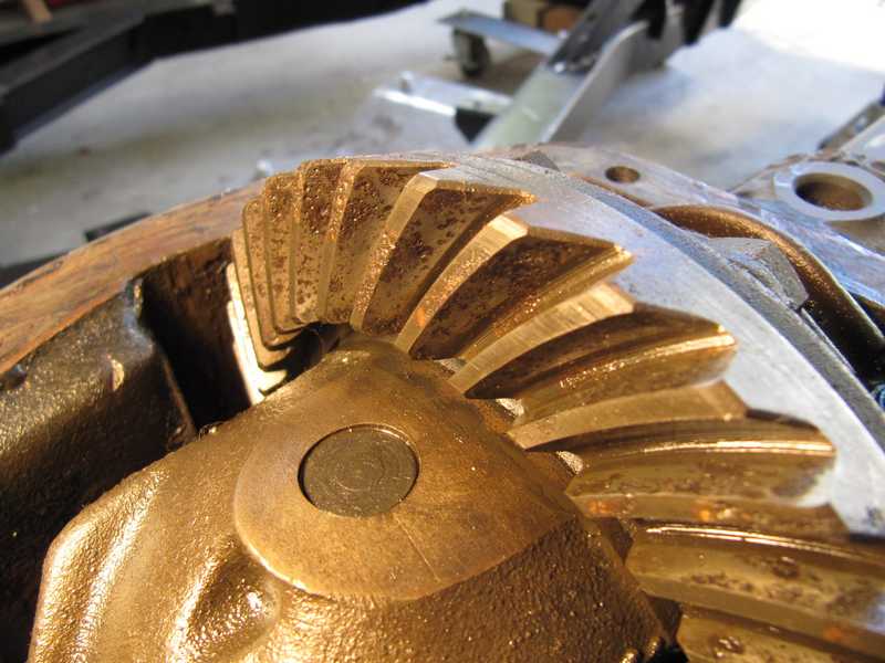
The pinion gear looked OK, but that's little comfort, as the ring and pinion gears are a set and must be replaced together.
I suppose we could view this as neglect, but if so, it was abetted by Triumph. The shop manual states that the differential oil should be topped up regularly but never replaced, and the differential has no drain hole. I doubt that the oils of the 1960s were good for 100,000 miles of use, as the oils available today certainly aren't. There should have been a replacement spec (30,000 miles is typical) and a drain plug.
While new ring-and-pinion sets are available, they are expensive ($450 at this writing), so I started by buying a used set. The carrier, which came with the gears, was also in better shape than my old one, so I replaced it as well. I replaced all bearings with new Timken ones, purchased from a bearing supplier at about half the price of the British-car parts suppliers. Of course, all seals and such were likewise renewed.
After finishing the differential, I found that I could not get a good pattern with gear-marking compound unless the backlash was set to a value that was much too great. For that reason, I had to rebuild the differential with a new gear set.
Technical Notes on the TR Differential
Basics
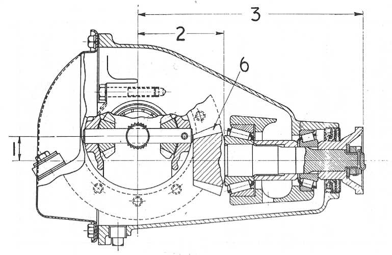
There are four adjustments in setting up any differential: the position of the pinion in an in-out direction, the position of the ring gear in a right-left direction, and the preloads on both sets of bearings. In the Triumph differential, the pinion position is adjusted by shims (23) underneath the inner pinion bearing (22), and preload by shims (26) under the outer one (25). (The numbers are those of the exploded view of the differential on
p. 3-108 of the shop manual, reproduced below. It represents the solid-axle cars; the IRS cars' differentials have virtually, if not literally, identical internals.)
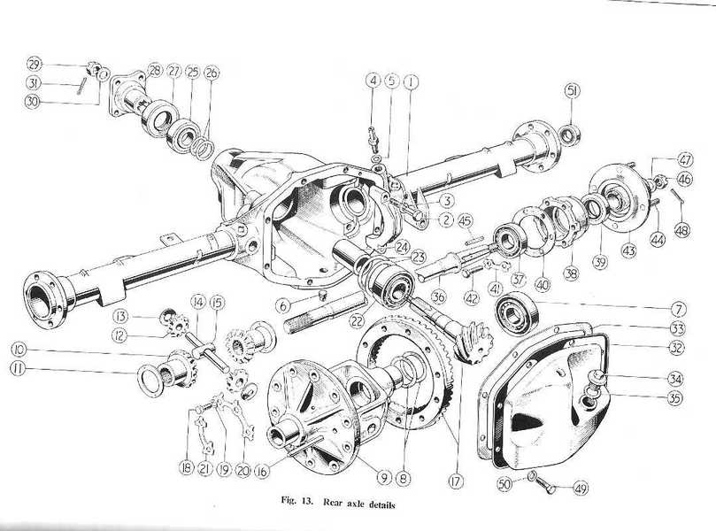
The ring gear carrier (9) has shims (8) between the carrier and the bearings (7). While the figure shows them on only one side, they are fitted to both. Since the ring gear is on the left, as viewed from the rear, the left-side shims adjust its position. The right-side shims are selected to fill the remaining space and to provide preload. There is a little interaction between sets of shims; preload shims affect location at least a little and, of course, the locating shims affect preload. This behavior just adds to the enjoyment of setting up the differential's gears.
Differentials are a pain to restore. They invariable require special tooling that is no longer available, and adjustment shims may or may not be available. The differential requires laborious disassembly and assembly and painfully careful measurements, which must be repeated many times to get the shims right.
If they are unavailable, shims often can be made from steel shim stock. Packets containing sheets of shim stock in an assortment of thicknesses are readily available, but at this writing (late 2017), all differential shims are still available from the usual suspects at reasonable prices.
Pinion Setup
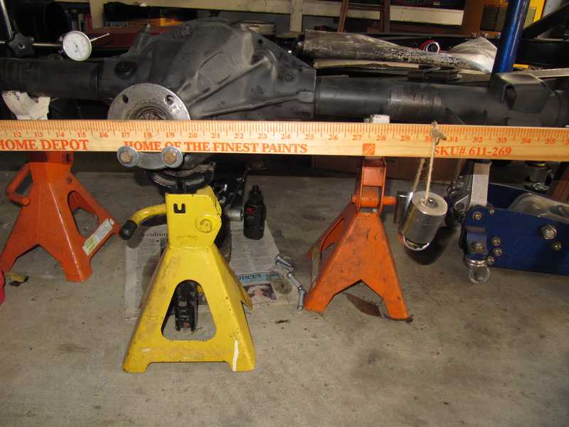
A critical part of setting up a differential is the in-out position of the pinion. As with most other differentials, a special tool is used to measure that position. There is very little chance of finding that tool, however, so it's best to forget it exists. The good news is that the shop manual lists the necessary dimensions (p. 3-102, reproduced below), so all is not lost. Dimension (2) in that figure is the critical one, 3.437 to 3.440 inches, measured from the center of the axle to the surface where the pinion head mates with the inner bearing.
In spite of the tight tolerances, the depth spec, above, is not the whole story. The pinion is often marked with a correction number, which should be added or subtracted from the specified depth. Also, the shop-manual specs apply only to new gears; because of wear, they might not be valid for used gears. For example, setting a used gear to the new-gear backlash spec probably will put the gear too close to the pinion.
Measuring this dimension correctly invariably requires fabrication of a few special tools. Figuring out what to make and how to do the measurement, without the factory tools, is a test of creativity.
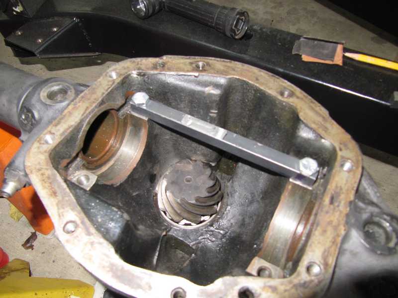
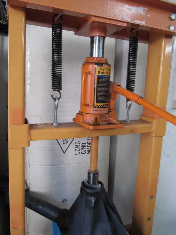
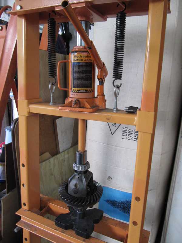
Once the pinion position is set, the preload must be adjusted. The correct preload in many cars is defined by the drag on the pinion as it is moved; this is true of the TRs as well. Correct preload is indicated by a drag of 15 to 18 pound inches measured at the pinion flange. One can use a low-value torque wrench to measure it, but a simpler method, illustrated here, involves bolting an arm to the flange and adding weights so that the torque equals the desired value.
In the TR differential, the preload and position are adjusted by different sets of shims, so theoretically they are independent. I found that the preload affects the position somewhat, so the position should be measured with the correct preload.
Ring Gear Setup
To set the left-right position of the ring gear, one first must measure its looseness without shims or the pinion in place. The total thickness of the shims, (i.e., the sum of all the shims on both sides), is that required to fill up the space, plus a specified 0.003 inches for preload. The measurement is made by installing the differential carrier without shims, moving it side to side, and measuring that movement with a dial indicator. This is an easy measurement to make. Take that measurement, add three mils, and that is the total thickness of the shims in the two shim packs. If we add a shim to one side, we must remove the same thickness shim from the other.
The second measurement is made with the pinion in place and adjusted. The carrier (with both bearings but no shims) is moved sideways to find the distance to the "full mesh" position, the point where the ring and pinion gears are fully meshed. Then, spacers are chosen to achieve the specified backlash, 0.004 to 0.006 inches at the outer edge of the ring gear. The shop manual implies that one mil of backlash corresponds to one mil of shims, so the shim pack should be about 5 mils thinner, on the left, than the full-mesh measurement. At this point we have the total thickness of both shim packs and the thickness of the left pack, so the right is just the difference between those values.
This backlash specification is for new gears. Used gears generally have more backlash, and when the differential is serviced (say, to replace a bearing), it is probably best to set them up for the same backlash, even if it is greater than the spec. (I discovered this the hard way.)
Lubrication
Lubrication of a TR differential is a dilemma. If it contained no brass or bronze, the TR differential could use any ordinary hypoid oil of the correct viscosity. In fact, the differential has two brass thrust washers, so the use of ordinary oil is a concern. GL4 transmission oil, which does not corrode brass, is probably not a good choice, as it is not designed for the high pressures in the differential. High-pressure, sulfur-free gear oils are available, and many of the common gear oils are acceptable as well. Information on these matters is usually provided on manufacturers' web sites.
I use Swepco 201 in my Porsche transaxle, a high-quality 80W-90 gear oil. The manufacturer states that is is fine with yellow metals, so I planned to use it in the TR as well.
In general, the oil in any differential should be checked and replaced periodically. The TR shop manual is equivocal about replacing the oil, however; the maintenance schedule specifies oil replacement every 6000 miles (almost certainly an error, because this is far more often than necessary), but elsewhere states that the oil never needs to be replaced, just topped up! Presumably for that reason, the differential has no drain hole.
Even though differential oil isn't subject to the severe service that engine oil experiences, it still is subject to oxidation, which can cause it to become corrosive. It's a safe bet that the folks at Triumph, who downplayed differential oil replacement, didn't expect the car to be in service 50 years later. Typical intervals for transmission and gear-oil replacement are around 30,000 miles, so it's probably a good idea to replace the oil after that interval. Since the differential housing has no drain plug, replacement requires either a suction gun or removal of the back cover. Some people drill and tap a drain hole when the differential is apart for service or rebuilding.
Tools
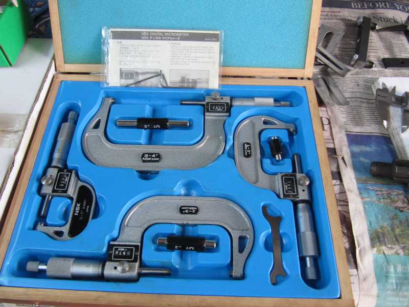
Although the shop manual describes many special-purpose tools, most can be replaced by ordinary, general-purpose tools and simple homemade ones. One of the latter is a case spreader, which is necessary for removing and installing the differential carrier. General-purpose bearing tools and pullers can be used for removing and installing the bearings. Three particular necessities are a dial micrometer with a magnetic holder, a one-inch caliper micrometer, and a six-inch dial caliper. These are measuring tools that anyone restoring a classic car should own. A depth micrometer would also be very useful, but I did not have one at the time I restored the differential. Although I made my own equivalents, a few machinist's parallels and gage blocks or 123 blocks would also be helpful.
Case Spreader
In the TR, the preload on the carrier bearings (7) is provided by making the width of the carrier 3 mils larger than the space provided for it. The preload is thus created by the case. Extracting the carrier, therefore, requires stretching the case by at least 3 mils to remove the preload. The case is big and solid, so stretching it even three mils takes some effort. The shop manual shows a picture of the factory case-stretcher; fortunately, it is a simple device, and it is not difficult to make a tool that serves its purpose. Most importantly, the tool must be strong enough to handle the large forces that it experiences.
I should note that some people remove and replace the differential carrier without the use of a spreader. That requires prying the carrier out of the case and forcing it back in. While I don't doubt that is possible, it seems a little brutal to me. And the case stretcher was not expensive or difficult to fabricate.
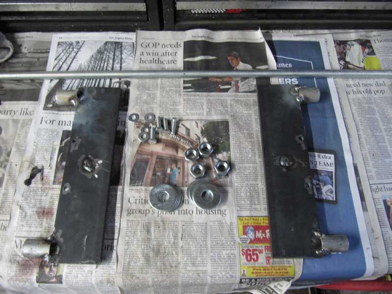
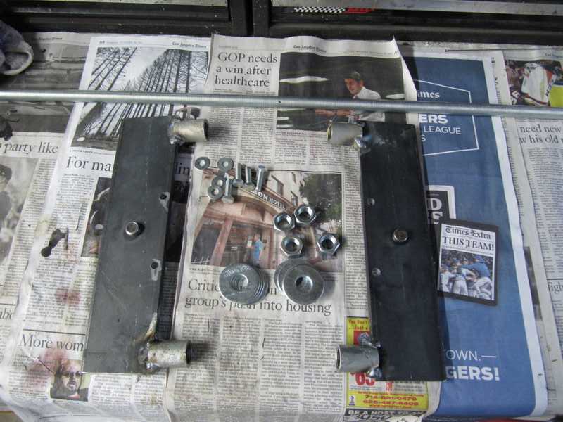
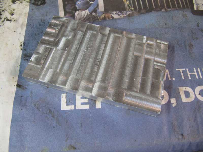
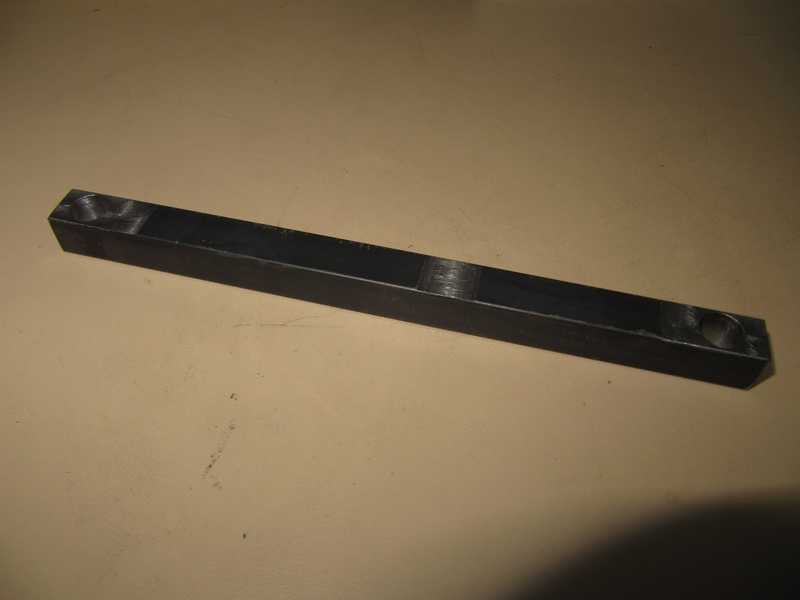
I made my case spreader from two 3 1/2 x 12 x 3/8 inch mild steel plates and used 3/4-inch pipe nipples as receivers for the threaded rod. To make sure the receivers were centered on the plate, I milled a shallow 3/8-inch-wide slot in one end, and to support the force on them, I squared the opposite end by turning it in a lathe. The force on the receivers is against the plate, not the weld, but I still used quite a thick weld for them, as it's possible that they may experience some significant off-axis force. The 5/8-inch diameter buttons, which mate with holes in the differential case, were made by rounding the heads of 7/16-inch screws in a lathe; the mating holes in the plates were drilled and tapped, then slightly countersunk. The modified screws were threaded in and welded on the opposite side.
The holes for the 5/16-inch screws were drilled slightly oversize. The screws are a little loose in the holes, as their purpose is just to hold the plates flat against the differential housing, not to take the spreading force. (This differs from what you might read on the internet.) The main part of the spreading force is taken by the 5/8-inch buttons. That's how differential spreaders are designed to work; in fact, many commercially available spreaders have only the buttons.
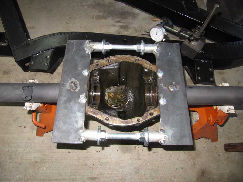
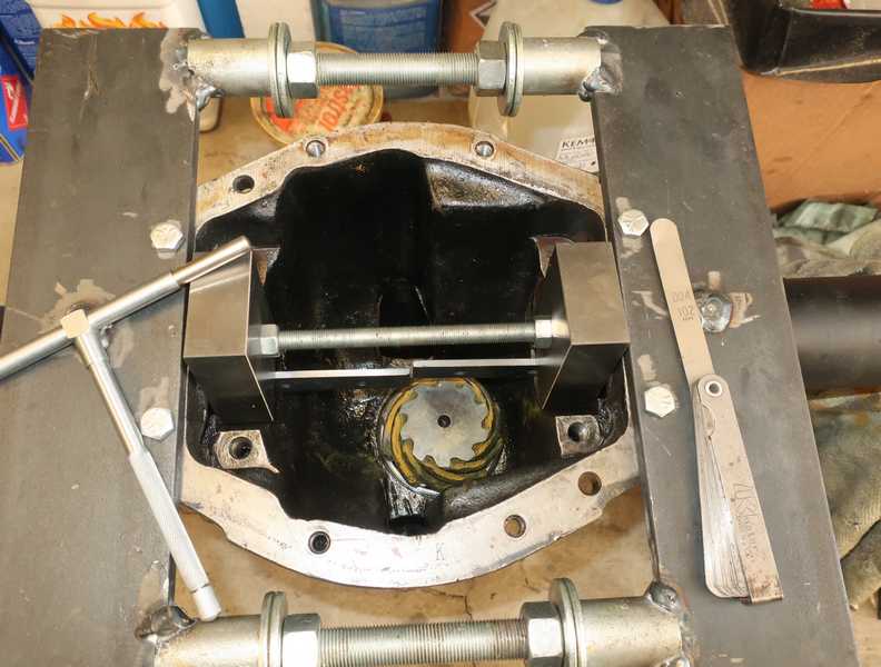
The pictures below show the finished plates. The threaded rod, which is 5/8-inch UNF, has not yet been cut.
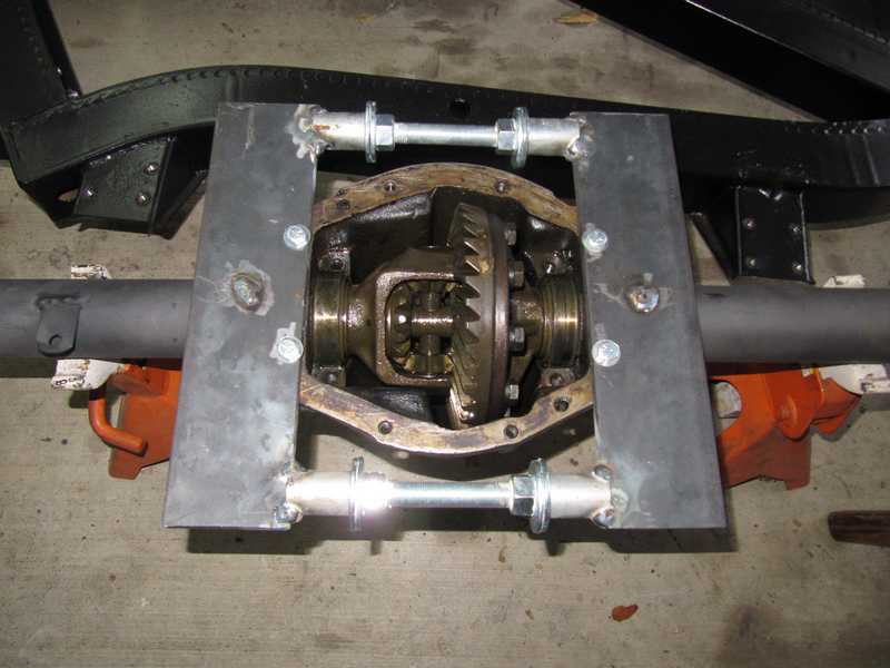
Below, it's finished and mounted on the differential.
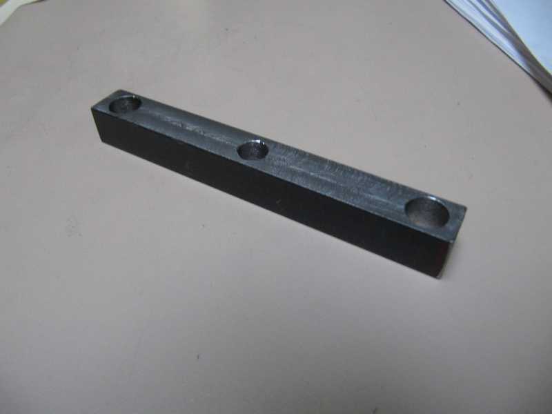
Pinion Inner Bearing Race Remover
This tool is pretty simple: just a block of aluminum, machined to 4.0 x 2.40 inches, 0.375 thick. It works better than an ordinary drift, as it largely prevents damage to the shims. I just insert it into the slots in the housing and use a press to push the race into the housing. If the corners of the block get damaged from the force, I simply trim them square again.
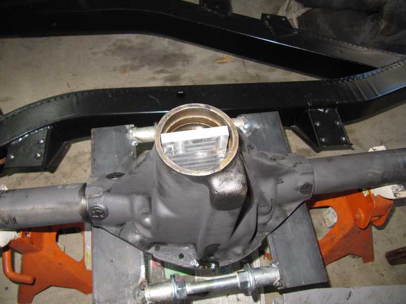
This tool requires that the outer race be removed in order to get to the inner one. It might be possible to prevent this by narrowing one end of the block so it could be tilted a bit on insertion, but I didn't try that. The outer race is easy enough to remove and to install.
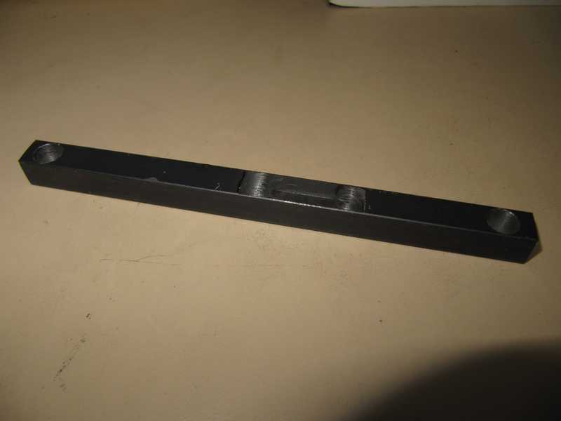
Depth Measuring Tools
The spec for the pinion depth allows for a range of only 0.003 inches between the depth limits. Accordingly, most measurements must be made with a tolerance on the order of 0.001 inch. That's a tall order; I doubt that the spec was even met by the factory. But we still can get close to it.
A set of depth micrometers is probably the preferred tool for many of the necessary measurements. At the time I did this work, I didn't have one, but I did have a good dial caliper and a milling machine. The tool below fits the dial caliper, holding it perfectly vertical and perpendicular to the measurement surface. In effect, it mimics the operation of a depth micrometer.
There are a couple of depth measurements that must be made accurately. These are needed for determining the distance from the center of the carrier to the pinion's rear surface. One is from the mounting surface of the carrier bearing caps, which is used as a datum, to the bottom of the bearing recess; the other is from that datum to the top of the pinion. More on the details of those measurements below.
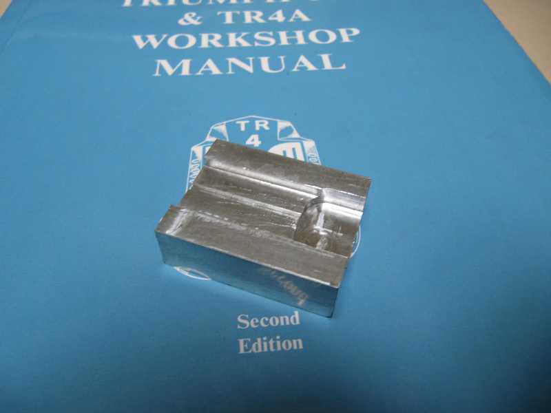
These tools are simply pieces of 1/2 x 1/2-inch steel which have been machined carefully to a flatness and constant thickness of better than 2 mils. 3/8-inch mounting holes are drilled at each end. The tool shown below, for measuring the bearing recess, has a 5/16 inch hole precisely at its center. I had planned to use that to locate the dial caliper, but that wasn't accurate enough. Instead, I used the block shown above.
It's important to note that the bearing-cap mounting surfaces are not centered; they are a few mils below center. Thus, it is necessary to measure that offset and include it in the pinion-depth calculations.
The second tool is similar, but it spans the width of the case, allowing a similar measurement that determines the depth from the datum to the pinion head. Flats are machined for the mounting surface and for placing the dial caliper. There is an additional flat on the underside, level with the mounting flats, used to measure the bar thickness. I made a couple versions of this tool before I was satisfied with it.
The thicknesses of the bars at their measurement points are measured with a micrometer.
Temporary Outer Pinion Bearing
Here is a cute trick for making the job a little easier. Correct measurement of the pinion depth requires full preload on the pinion. To adjust the pinion depth, one must set the preload temporarily by installing the outer bearing and flange, without the spacer, and tightening the flange nut until correct preload has been achieved. Getting the depth right invariably requires several disassembly and reassembly operations. It's a lot easier if the outer bearing does not have to be pressed on and off each time a change is made.
I found an old bearing that was in moderately good condition and ground its inside to make it a sliding fit on the shaft instead of a press fit. That way it could be installed and removed easily. It was good enough that I could set the preload on the pinion temporarily. Of course, the correct bearing is needed for final setting of the preload.
Disassembly
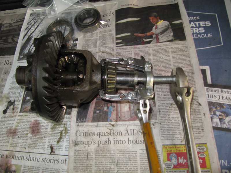
The picture below shows the spreader in use. I used plenty of grease on the threads and the large washers, then turned the nuts with two large crescent wrenches. To keep the forces balanced, I turned the nuts on opposite sides equal amounts; two flats on one side, then the same on the other. It is possible to damage the case when doing this, so it's necessary to use only enough force to loosen the differential. I probably used more than necessary, but the case seemed OK afterward, and the carrier came out easily. Next time, if there is one, I won't be so brutal.
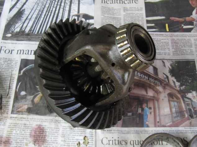
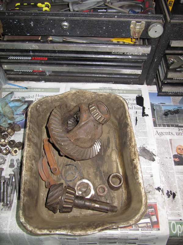
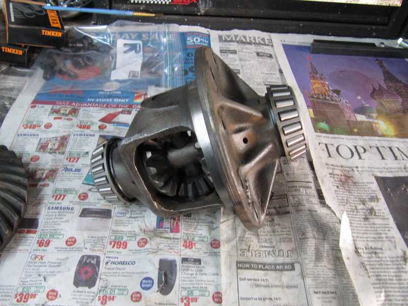
Below are some pictures of the carrier. At first glance, it wasn't too bad. The internal differential gears looked OK. The bearings should be a press fit, but the left-side one, although not loose, was only a sliding fit on the carrier. That was a concern, although I later learned that this situation is common.
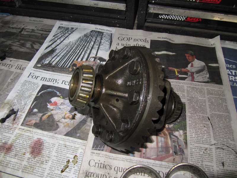
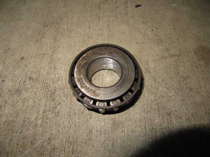
As I expected, the carrier-bearing races had substantial corrosion; the bearing rollers were similarly corroded. I found no date code on the bearings, but it's likely that they were originals.
The right-side bearing wasn't as easy to remove. Under the edge of the bearing, the carrier has a pair of convenient notches, which allow the use of a small two-jaw puller. With some effort, the bearing came off. The left side had 40 mils of shims; the right side, 35.
Once the carrier was out of the way, the pinion was easy to remove. The pinion's outer bearing cone, which should be a press fit, just slid off; the inner one came out with the pinion. The bearings' outer races were more difficult, as they had to be taken out with a drift. The front bearing's race was removed easily. The rear one has a reputation for being difficult, but the use of the tool described above made the inner-race removal fairly easy.
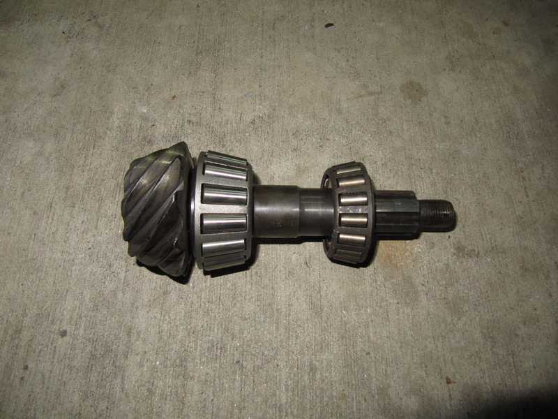
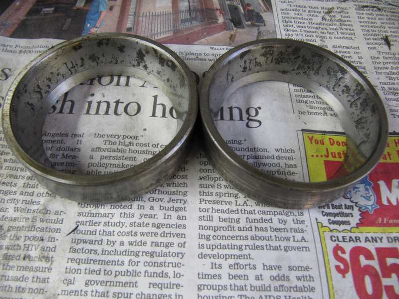
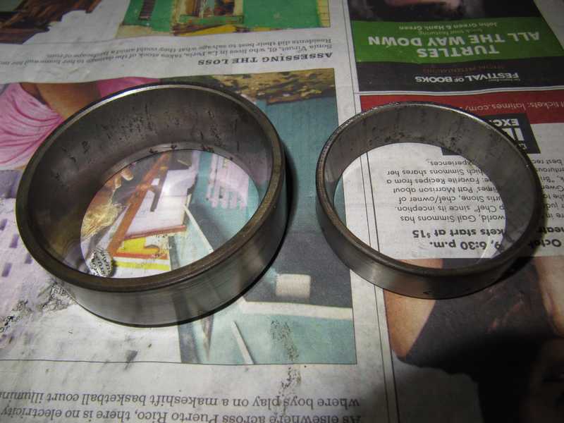
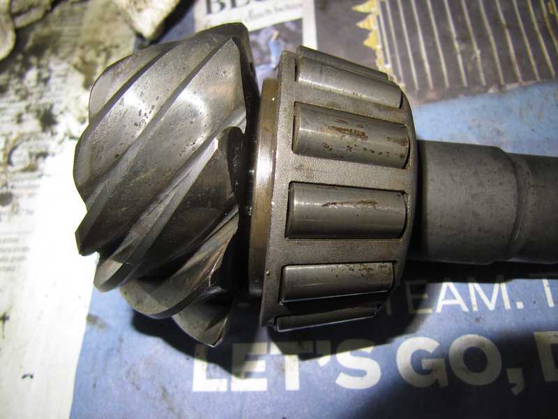
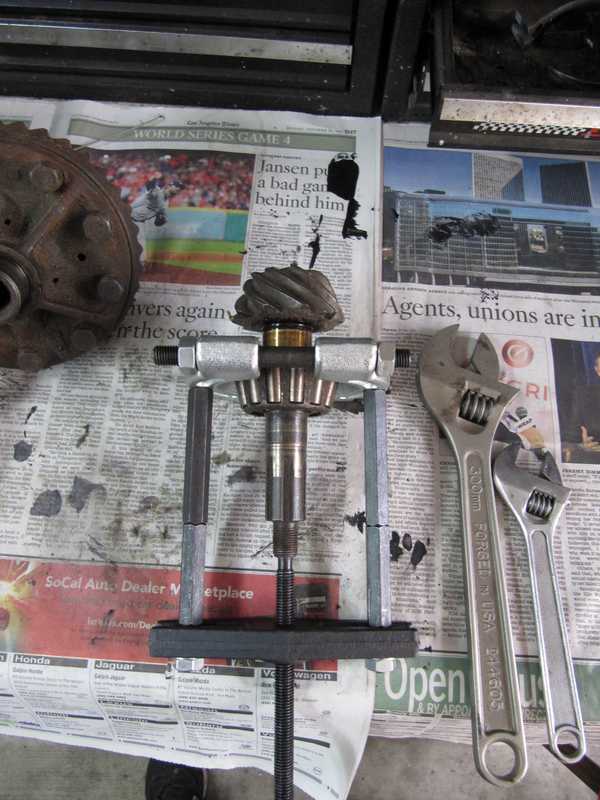
Below, the pinion-gear races. They were not as bad as the carrier races but were still due for replacement. The second picture shows the pinion and inner bearing. The pinion was worn, not as badly as the ring gear, but (in my opinion) beyond use. In any case, it had to be replaced, as the ring gear and pinion are a matched set. Removing the inner bearing is tricky. The special tool described in the shop manual is no longer available, and a general-purpose bearing separator often won't fit. This pinion was trash, though, so in this case it didn't matter.
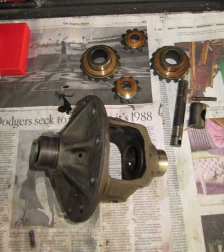
I removed the planetary and star gears, inside the carrier, to check the condition of their thrust washers. All were fine, but I could feel a very little backlash in the internal gears. Oddly, there is no spec in the shop manual for backlash; the manual just instructs us to minimize it by selecting thrust washers of various thicknesses. I measured the thrust washers, but their thickness was the maximum available, so it was impossible to reduce the backlash by using thicker washers.
The rest of the differential, disassembled, is shown in the second picture. The item on the far right in the second picture is the (probably) original leather pinion seal. An antiquated component if there ever was one.
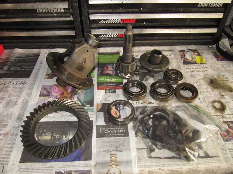
I bought a used unit, mainly for the ring gear, which was in much better condition. The carrier and internal gears looked better than the original ones, so I decided to use it instead of the original. The bearings came off without too much difficulty; the left-side carrier bearing was not very tight, but at least it was not a sliding fit, like the one on the original differential. I was able to remove the inner pinion bearing with an ordinary separator.
Reassembly and Setup
Bearing Recess Depth
Dimensions in the above drawing are from the center of the carrier, but it's impossible to measure that center directly. Instead, the mounting surfaces for the carrier-bearing caps are used as a datum, but there is no guarantee that those surfaces are centered with the bearing, and thus the carrier. To find the offset, we measure the distance from that datum to the bottom of the bearing's mounting surface and compare it to the known radius of the bearing. The difference between those values--the recess depth minus the bearing radius--is the datum's offset.
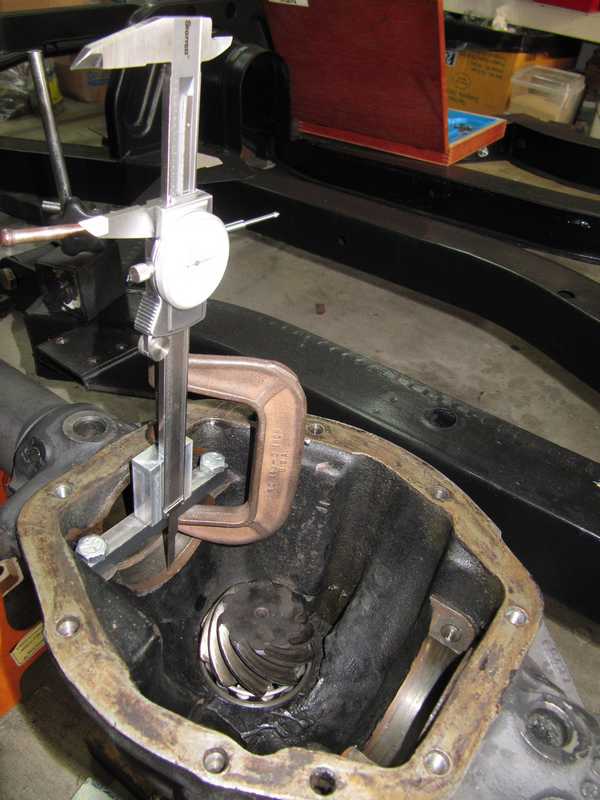
This is done with a dial micrometer and the special tool I made, an accurately machined and measured crossbar. This measurement is tricky: it is essential to make it precisely at the center of the recess. The bar thickness is measured with a micrometer and subtracted from the raw measurement to obtain the recess depth.
I found that it's just as accurate, and easier, to hold the caliper while making the measurement. The clamp shown in the picture below is one way to do it, but it often just gets in the way.
I determined that the datum was 0.006 inches below carrier center on the left and 0.008 on the right.
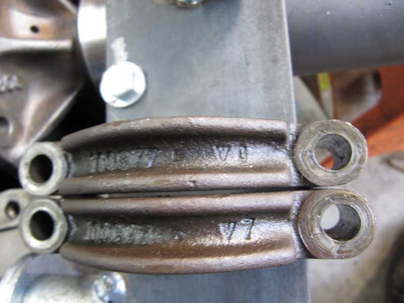
Mostly out of curiosity, I measured the depth of the bearing caps. I obtained 0.005 inches over the center depth on the left and 0.007 on the right. The caps were marked with a cryptic symbol, as shown below; the left one, marked "∇6" is at the top, and the right one, marked "∇7" is at the bottom. It seems that the caps may have been selected in assembly to match the depth of the bearing mount, minus one or two mils, so the bearing could be clamped tightly. If so, this provides a clue as to how far the bearing mount is below the center of the bearing.
Carrier Bearings and Carrier Float
The next measurement is the side-to-side carrier float without bearing shims. that value, plus 0.003 inches for preload, is the total thickness of the two carrier-bearing shim packs.
I began by pressing my new bearings, without shims, onto the carrier. They had to come off again, several times, to install the shims and adjust the position.
Measuring the carrier float seems simple; just install it, without shims, set up a dial micrometer, and slide the carrier back and forth. It's actually not quite that easy, as an accurate measurement requires that the bearings be loaded at each end of the movement, and that there be no motion perpendicular to the carrier's axis. To guarantee that, I installed the bearing caps and tightened the mounting screws only finger tight, then backed them off about 1/8 turn. That allowed the bearings and races to slide back and forth without restriction but also without any vertical motion. I used a couple of screwdrivers to move the carrier and bearing, and to provide sufficient load on the bearing. With the carrier fully to one side of the housing, and with the bearing loaded, I zeroed the micrometer; then I moved the carrier to the other side, loaded the other bearing, and noted the change measured by the micrometer. As with all measurements, I did this a couple times to make sure it was right.
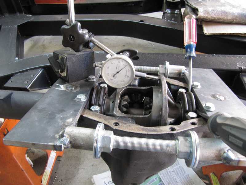
While I had the carrier in place and the bearings loaded, I checked the runout at the ring-gear flange. It was less than 0.001 inch; the spec is 0.002.
Pinion Setup
Once the carrier float has been determined, the pinion can be installed and set up. The first task is to set the pinion depth, which is adjusted by shims under the inner pinion-bearing race; the second is to adjust the preload.
To set up the pinion, the inner bearing cone is first pressed onto the pinion gear assembly; that's straightforward. It is important in this bearing-installation operation, and all others, to make certain that the bearing or race is pressed ALL the way to its stop. It's easy to stop a few mils short. Then, in use, the bearing eventually moves all the way to the stop, and all previous measurements and shim adjustments are worthless. Getting those last couple of mils can require a lot of force, so it's best to use a hydraulic press for installing bearings.
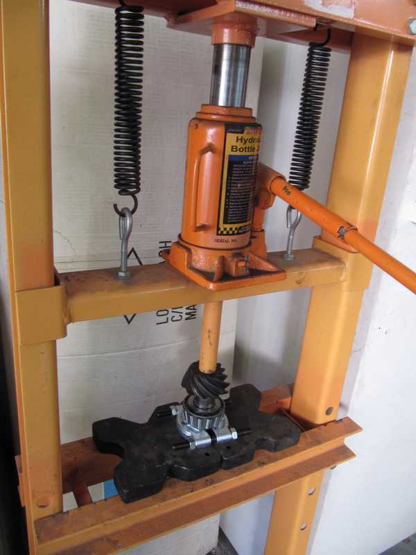
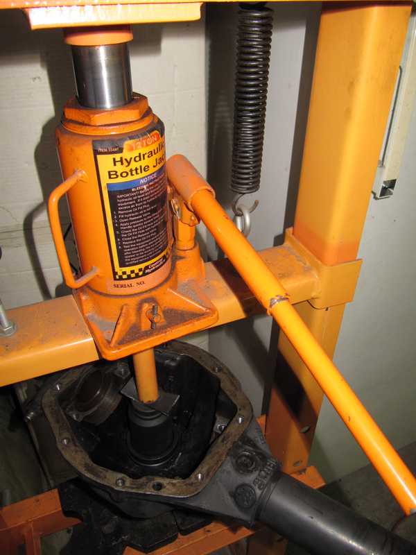
Pressing the inner race into the housing has a reputation for being difficult, and it must be inserted and removed a few times in setting up the pinion. Part of the problem is the shop manual's implication that a screw-operated bearing setter is adequate for pressing the race into the housing. While the original special tool might have been adequate, the general-purpose tools available today are not. It really requires a hydraulic press.
The race gets cocked easily while being pressed into place; it is difficult to get it to go in perfectly straight. The best method, I found, is initially not to worry about straightness, but, as soon as the race starts to tilt, to move the force to the high side. That straightens the race. Once it is straight, even force can again be applied, and the bearing goes into place fairly easily. The housing is large and awkward, and it is cumbersome to lift onto and off the press, but I don't think there is any other workable way to insert this race.
Only the inner race has shims under it; the shims for preload go between the outer bearing cone and the spacer. With the use of the tool described above, pressing out the inner race, to insert shims, was easy. To insert the tool, I first had to remove the outer race. The outer race was not particularly difficult to insert and remove, though.
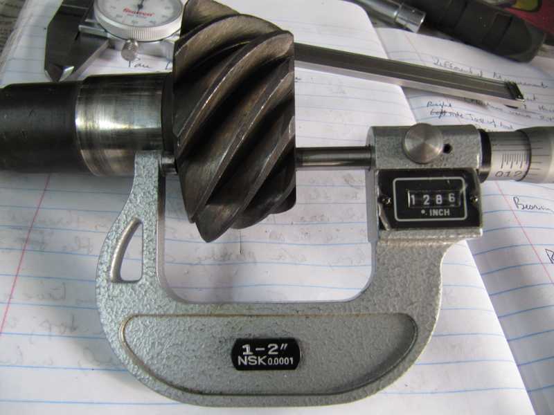
I have a nice set of micrometers, which I bought while working on my MGTD. I used them, among other things, to measure the pinion thickness, another important quantity, 1.286 inches in this case.
I measured the pinion depth in a manner similar to the bearing recess depth, using the dial caliper to measure from the top of the crossbar to the pinion. The pinion depth must be measured with full preload on the bearings. To set the preload, the outer bearing, I installed the pinion flange, washer, and nut, leaving out the spacer that normally sits between the two bearings. I then tightened the flange nut enough to load the bearings to the specified value. That preload was surprisingly great; the pinion seemed uncomfortably tight. I found that, when the preload was correct, tightening the nut a little more did not change the pinion depth.
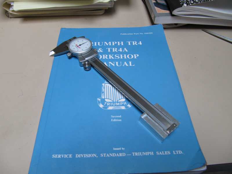
The preload is correct when the torque required to move the pinion is 15-18 pound inches (without the oil seal, of course), a value outside the range of most torque wrenches. So, I made my own high-tech inch-pound torque wrench, shown below. The sockets were weighed on a digital scale and are within a couple percent of one pound. Note that the yardstick is centered on the pinion nut, so it has no effect on the torque.
The preload torque must be measured with the flange nut fully torqued (125-145 lb ft).
It was a simple calculation to determine the distance from the carrier center to the bearing-contact surface of the pinion gear, dimension 2 in the figure.

The correction for the raw measurement, in my case, was as follows:
Bar thickness: -0.489
Datum to carrier center: +0.007 (average of the two sides)
Pinion thickness: +1.286
Adding these gave a +0.804 inch correction. For example, suppose the above measurement was 2.630 inches. Adding 0.804 gives a value of 3.434 for dimension 2, which is 3-6 mils high. Removal of a 5-mil spacer should change dimension 2 to 3.439.
After a few changes of pinion and preload shims, I eventually got the pinion within spec. I ended up with a 45-mil stack of pinion shims and 43 mils of preload shims. The pinion depth was 3.438 inches (3.437-3.440 spec) and 15 lb-in of torque (15-18 spec). Setting up the pinion was one of the most tedious automotive tasks I've ever done.
Carrier Assembly
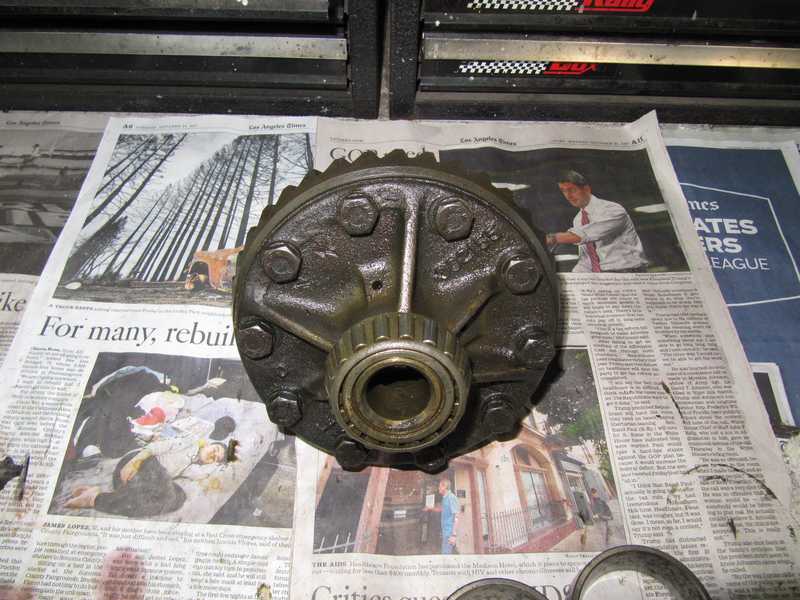
Since I didn't remove the differential gears, and the bearings had already been installed (temporarily, for the carrier-float measurements), assembling the carrier involved only installing the ring gear. It is important to make sure the ring-gear mounting surface is clean and free of debris, as tolerances are tight. I reused the old bolts, as they are a special type, hardened (equivalent to modern grade 8), with a short unthreaded shank that locates the gear on its mounting surface. Similar bolts would have been difficult to find, as most available grade-8 bolts of the required length are fully threaded. I did use new, grade-8 lockwashers, however. Uniform torque on those bolts is probably important; the manual specifies 35-40 lb-ft.
Carrier Setup
Now to set up the carrier. I set the backlash to the specified 4-6 mils, not realizing that wear in my used gears would necessitate greater backlash. Setting used gears to the specified backlash value inevitably moves the ring gear too close to the pinion. I didn't realize this until the setup had been completed. Anyway, here's what I did:
The first task was to measure the carrier float between its full left position and fully meshed position. This is called the "full mesh" distance in the shop manual; it is measured with the carrier bearings in place but without shims. I measured 47 mils with no shims under the bearings. I removed the left bearing, added 42 mils of shims, aiming for 5 mils of float and therefore backlash, and pressed the bearing back onto the carrier.
The backlash can be measured without installing the right-side shims; it is necessary only to push the carrier all the way to the left, thus loading the left bearing. When I measured the backlash, however, it was 10 mils. I rechecked the float, and it was 8 mils instead of the expected 5. What was going on?
The most likely explanation is that the bearing wasn't fully pressed onto the carrier when the measurement was made. If that was the case, the total float measurement would also be erroneous, but it can't be remeasured without removing the pinion or the ring gear. It would have been a cold day in hell before I did that. Anyway, I changed the left shim stack to 46 mils, and measured 6 mils of backlash (the spec is 4-6 mils). So far, so good. But the measurement I needed to set the right stack, and thus the preload, was suspect. What to do?
I installed the carrier, loaded it to the left, and measured the right-side gap with feeler gauges. I measured 28 mils. Adding all this implies that the float originally was something like 74 mils instead of the 63 I measured. I have a hard time believing that this was caused by the bearings not being fully home; I think I would have noticed 11 mils of gaps between the bearings and carrier. Perhaps the measurement was really 73 mils, but I read 63. I've done dumber things.
Knowing the gap, I set the right-side stack to 31 mils. I tested it by trying to insert the carrier; it went in a little way and jammed, as I would have expected.
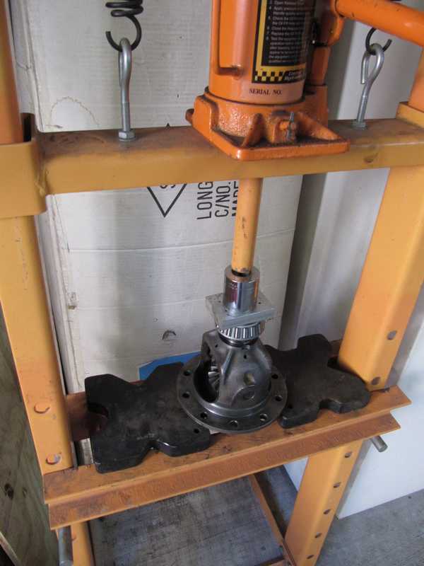
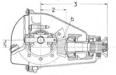
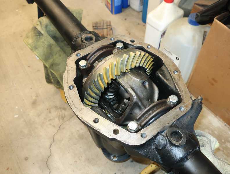
I hauled out my case spreader, spread the case, and dropped the carrier into position. I installed new bolts for the bearing caps. Finally, I rechecked the backlash and measured 5 mils. Below is the finished differential.
Second Try
I made a mistake by not checking the gears with marking compound before installing the rear cover. If I had, I would have noticed that the mesh wasn't right.
When I got the car on the road, I noticed a "howl" from the drive train. Simple tests showed that it was clearly a problem with the differential. I drained and removed the rear axle, then checked the ring and pinion gears with gear-marking compound. The marks indicated that the pinion position was probably OK, or close to it, but the gears were too far into mesh.
Although moving the ring farther out of mesh would put the backlash out of spec, I tried it anyway. By time I got a halfway decent pattern in the marking compound, the backlash was 20 mils, and it really looked like the ring had to be moved out even more! What was wrong?
It seemed to me that the most likely explanation was that my used gears were too worn, even though a visual inspection showed no obvious signs of wear. After all, the gear surfaces would have to wear only about 4 mils each for the backlash to increase from 5 to 20 mils; I doubt that would be easy to see. Since I had set the backlash to the specified 5 mils, assuming that the gears had minimal wear, I had actually moved the gears too far into mesh.
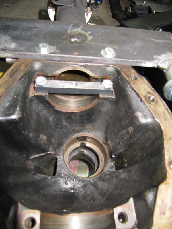
Another concern was possible distortion of the case caused by repeated use of the stretcher, especially because I probably had stretched the case more than necessary the first time I did it. I used the parallelism of the carrier-bearing surfaces as a check on the case straightness. I placed two 123 blocks against the bearing surfaces and held them in position with a length of threaded rod. I was careful to locate the blocks so they pressed against the bearing surfaces only, and I made sure that those surfaces were clean.
I found that the tops of the blocks were only 0.004 inches farther apart than the lower ends. I have no spec for this, but I can't imagine that four mils would be a problem. In any case, this is a difficult measurement, and the 4 mils was probably within its tolerance.
The cure, then, was to source a better ring and pinion. Unwilling to take another risk with a used part, I chose to repress my instinctive frugality and buy a new gear set, and, of course, I resolved that the new set would be checked carefully with gear compound before being put into service. The new set is made by Bastuck, a German manufacturer. I doubt that there is more than one supplier.
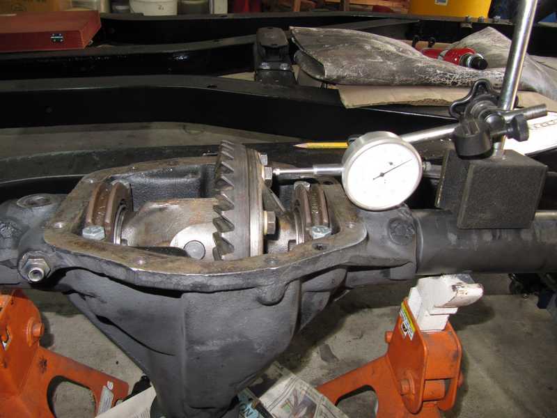
The new gear set could not be set up in the manner described above, because the spacing between the outer end of the pinion and the bearing surface, the measurement shown here, varied by 20 mils around the circumference of the pinion. Instead, I had to adjust it entirely with gear-marking compound. Since the gears were new, it seemed that the 4-6 mil backlash spec should be valid, however.
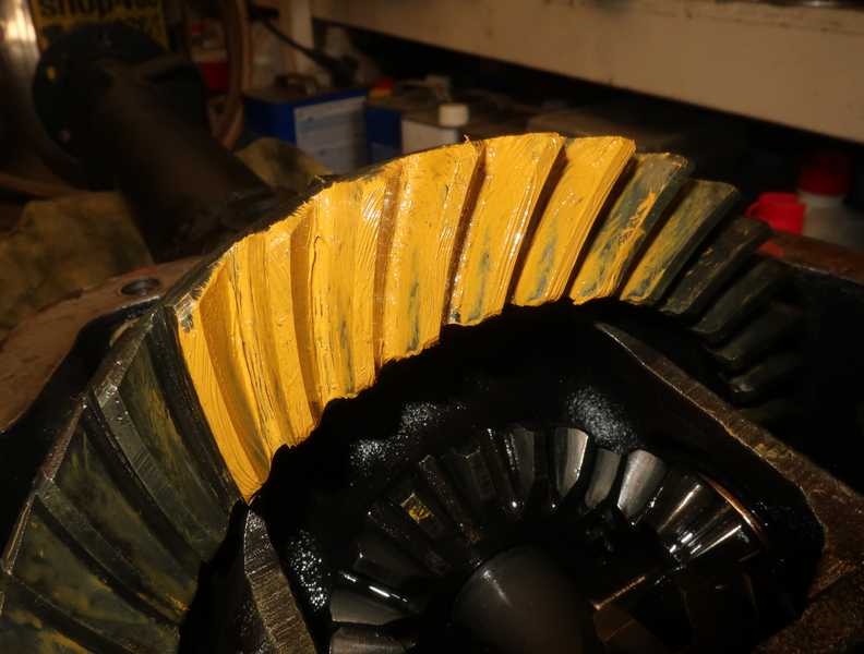
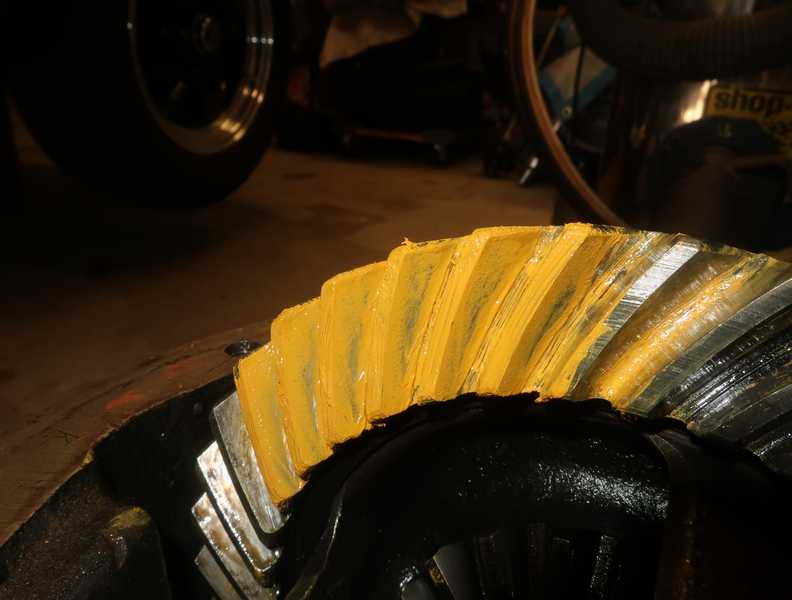
I started with the same sets of shims used with the previous gears, and they were actually fairly close. With a couple changes of shims, I obtained the patterns shown below, with 5.5 mils of backlash.
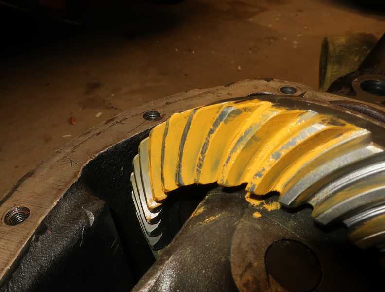
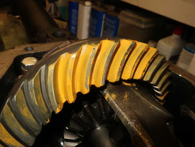
The markings in the photos are not very clear, but the pattern on the drive side extends almost the length of the tooth; on the coast side, it is a little toward the toe but still OK. I'll take it.
As long as the pattern is measured with adequate pinion preload, it really should not change when the differential is completely assembled. I made a final check of the pattern and backlash after assembling the differential, and all was well.
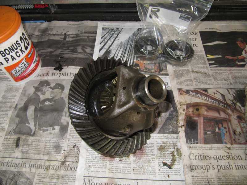
I wiped off most of the gear-marking compound. It's just a colored grease, so a little mixed into the gear oil is of no consequence. Below, the finished differential.
I reinstalled the axle with new lube, Swepco 201, an 80W90 hypoid gear oil which is compatible with yellow metals and popular among owners of early Porsches. I use it in my 1967 Porsche 912. I then road-tested the car; it ran as it should, with no "howl" or other problems. There was no perceptible gear noise.
Part Numbers and Dimensions
Here are some dimensions and part numbers, which might be useful to anyone benighted enough to contemplate a differential rebuild.
Timken Bearing Part Numbers
These numbers are a pseudostandard, as other manufacturers make identical bearings using the same part numbers.
Inner pinion bearing: 3188
Inner pinion bearing race: 3120
Outer pinion bearing: 15100 SR
Outer pinion bearing race: 15245
Carrier bearing: 16150
Carrier bearing race: 16283
Notes:
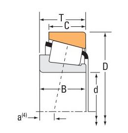
- The 15100 SR is the correct bearing for the pinion, but the 15100 is more readily available and is the one usually provided by parts suppliers. The most significant dimensional difference between those bearings is the protrusion of the center piece beyond the outer race,
B-T in the Timken catalog figure below. The 15100 has a 0.7 mm (28 mils) greater protrusion, so it requires fewer shims. If the 15100 is used, it is possible to encounter the unenviable situation where the bearing has no shims but still not enough preload. Then, one option is to find (or make) a 28-mil shim or two that fit under the outer race. Another option, if a lathe is available, is to take a 28 mils off the spacer that sits between the bearings. Other dimensional differences are probably insignificant.
- The rear (inner) pinion bearing is marked 3188S. I could not find a 3188S in the Timken catalog, but 3188 is listed and is readily available. I assume that the 3188S has been discontinued. Some non-Timken bearings sold as replacements are marked 3188, with no suffix.
Shim Dimensions
Carrier shims: 2.000 OD, 1.560 ID
Pinion front (preload) shims: 1.325 OD, 1.040 ID
Pinion rear (position) shims: 2.720 OD, 2.265 ID
These dimensions are in inches and come from measurements, not factory data, so they could be a few mils off. In any case, commercially available shims often have various outer diameters.
Pinion Seal
The new pinion seal I purchased from one of the major suppliers didn't fit. After some investigation, I learned that the part no. for the seal in the TR parts document is incorrect, and many suppliers, using that document, list the wrong seal. The listed seal is for the IRS differential, but the TR4A solid axle uses the same seal as the earlier TR4. The part number for the latter is 100898; the incorrect seal, the one that fits the IRS axle, is 140337. Timken seal no. 451857 also fits the solid-axle TR4A.