Capacitor Failure in Conventional Ignition
Systems
Steve Maas
Long Beach, California
The Problem
Because of repeated reports of failures of ignition capacitors (in this document, I'll use the modern term, capacitor instead of the antiquated one, condenser), I decided to investigate the cause by dissecting some failed units.
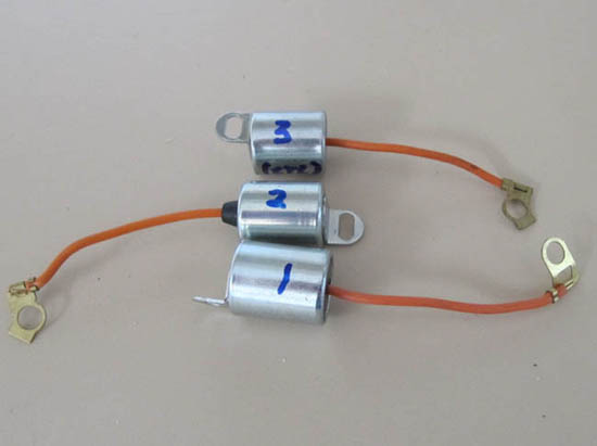
I examined three capacitors, two failed ones and a third, unused one, as a control. These were numbered 1 to 3; the unused one was no. 3. Nos. 1 and 2 were distinctly different, apparently from different manufacturers. No. 3 was marked "Made in England," so it could have been a Lucas product, but I'm not certain.
Electrical Tests
First, I tested all for open or short circuits. They all were OK. Next I checked the capacitance, and all seemed OK in this respect, too, with capacitances between O.20 and 0.22 microfarads (the spec is 0.18 to 0.25). Surprisingly, the "failed" units seemed to be working! I also checked to see if there was any breakdown. Since the ignition system can subject them to voltages reaching 250 volts, it seemed possible that the high voltage might have blown a hole in the insulation; this would not affect low-voltage measurements but might allow arcing at high voltages. I didn't have a high-voltage power supply to test this, but I did cobble together enough to get 175V. They all held up OK to this level.
Physical Examination
Next I disassembled them. I was looking for a sign of failure, such as arcing across the capacitor or through the dielectric. Here's where things got interesting.
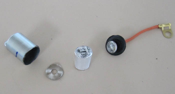
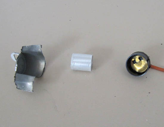
I started with no. 1. I ground off the edge of the case so it could come apart. Inside was a capsule (the capacitor itself) and a corrugated nickel-plated contact. The other contact was a brass washer to which the wire was soldered. The capsule, as I'll call it, consists of two layers of foil with a thin mylar layer between the metal layers. It's all rolled up into a cylinder with one metal layer sticking out one end and the other layer sticking out the other end. Electrical contact is made to the ends by simply squashing it all together. The capsule was smaller than the can in which it was mounted, so it conceivably could wiggle around a bit in response to shock and vibration. Not good.
This is a stunningly cheap, unreliable design. There is nothing to keep a consistent force on the capsule contacts; without that, there is no guarantee that the electrical contacts remain good, especially if the mylar expands and contracts with temperature changes. There should some kind of spring to keep the pressure on the contacts, but there is nothing even the least bit springy. The lack of any support for the capsule is also troubling, as it could move around if it doesn't fit tightly. That would also affect the electrical contacts.
This is all especially important, since the capacitor carries a surprisingly high current, about 4 amps, peak. This means that even a small additional resistance is likely to affect the ignition pulse and waveform, with serious effects on the operation of the car.
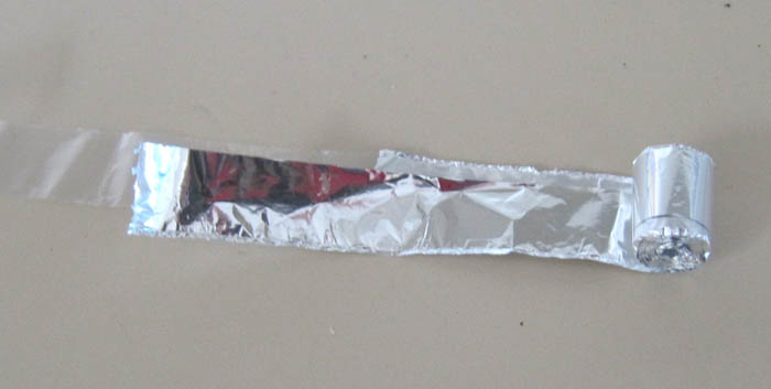
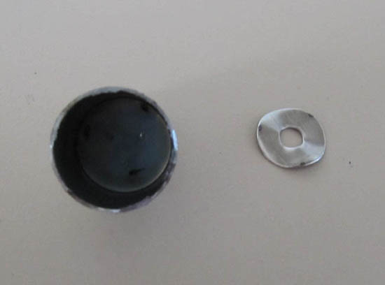
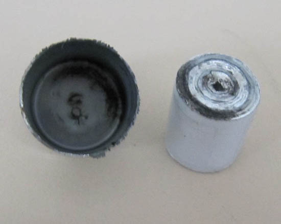
I started by unwrapping the capsule to look for signs of insulation breakdown. There were none. I then looked into the can and examined the corrugated washer; there I saw clear indications of arcing at the contact points between the washer and the can. This is shown in the second picture below. Although it's hard to see in the photo, especially inside the can, it is quite clear in real life.
No. 3, the presumed Lucas cap, was a little better quality, but not much. There were no marks inside it, which is no surprise, since it was unused. It had no corrugated washer, so the can-end electrical contact was simply to the body of the can, and the other contact was a brass piece that was crimped to the wire instead of being soldered. Again, the whole thing was simply squashed together with no spring of any kind to keep the pressure on the capsule. The capsule was also considerably smaller than the inside of the can, allowing it to move around quite a bit. Any such motion is likely to damage the electrical contact.
I finally opened no. 2, and that was a surprise as well. While its design was very similar to no. 3, it showed clear indications of significant arcing at the can end. Not only were there marks on the can, but there were marks on the capsule as well. It clearly had arced quite a bit.
Conclusions
It appears to me that these capacitors are failing because of an extremely poor design and equally poor manufacturing quality, resulting in an erratic electrical contact at the can end of the mylar/foil capsule. Since there is nothing to maintain pressure on the capsule, temperature variations and vibration eventually cause this contact to loosen, and the can end begins to arc. This creates additional resistance and may even cause an intermittent open circuit in the capacitor, which in turn results in a weak spark, burned points, and rapid ignition failure. It is also consistent with reports that new capacitors often seem to work well for a short period of time and then fail.
What to Do About It?
The poor quality of these components is more than a little disturbing. I view these capacitors as time bombs in the ignition system. The chance of one failing, sooner or later, is pretty high. Such sloppy manufacturing and design quality really should not be tolerated in cars that have enough potential reliability problems already.
The solution, of course, is to find an acceptable replacement capacitor, one that can handle the high current of an automotive ignition system. One good option is a "snubber" capacitor. These are designed for soaking up large voltage spikes in power electronic components, much like what the capacitor in an automotive ignition system should do. They are not cheap by capacitor standards, a few USD, but not expensive by automotive standards.
An Alternative Capacitor
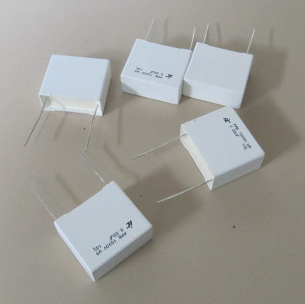
I found a good replacement capacitor for the unreliable ones that are currently being sold by the usual suspects. I got a few of them from an electronics supplier; the part is a polypropylene, metal-film capacitor, Illinois Capacitor no. 224PPB102K. There are others that should work; this one is overkill, for sure, but still is less than $3. And, it should last forever; no need to replace it periodically.
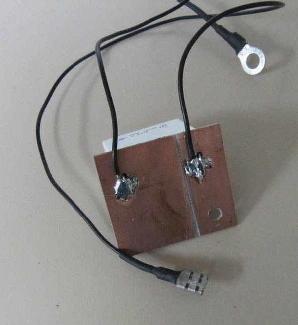
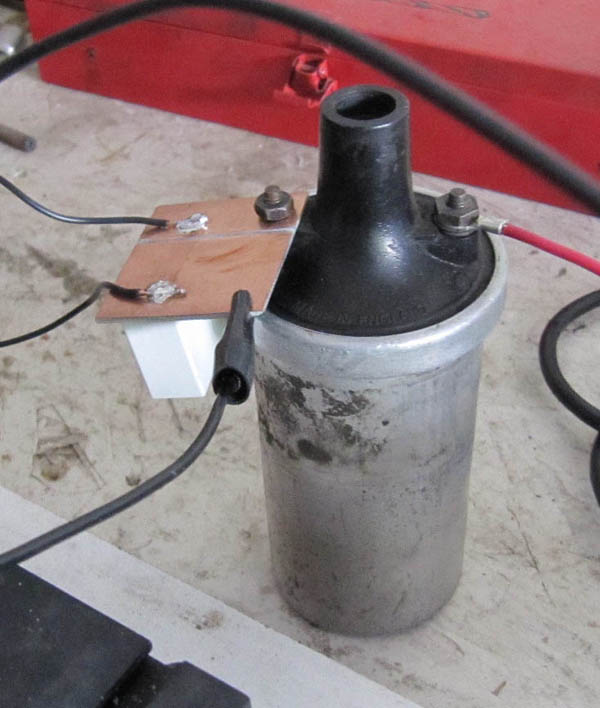
The picture below shows them. They are a little large, about 1.25" x 1" x 0.5", and definitely won't fit inside most distributors. I mounted the cap on a piece of printed circuit board (second picture) so it could be mounted right on the coil (third pic.) This is a little clumsy, and not terribly attractive; for many of you, that matters, so maybe a little more thinking about this is in order.
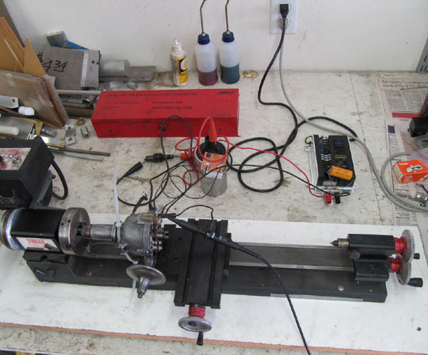
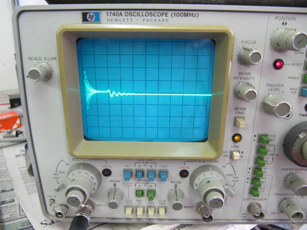
The next picture below shows the test setup. I mounted a distributor in my lathe, so I could spin it, and connected it to a coil and spark plug. I powered it from a 12V power supply. It all worked well; I could see the plug sparking and some sparking at the points as well. I was surprised at how little sparking there was at the points, but of course there can't be much, or they wouldn't last. The main reason for all this was to monitor the waveform at the coil, so I could be sure it was doing the same thing that the standard system does. I had measured the waveform in the car before converting to the electronic ignition, and I was pleased, but not at all surprised, to see that it was virtually identical (last picture).
So, I think that this idea works, and certainly should be lot more reliable than those depressing caps I took apart.
If you want to try this yourself, and can't find the exact capacitor I used, you might look for a capacitor of 0.22 microfarads, at least 600 volts dc breakdown voltage. If you can find a "dv/dt" spec, multiply this (in volts per microsecond) by the capacitance in microfarads, which of course is 0.22. This should be at least 5. If the catalog doesn't have that spec, which it probably won't, use a fairly large, polypropylene, metal-film capacitor (say, at least 0.5" dia by 1.5:" long). Anything this size should be husky enough to handle the current. The PPA series, which Allied also has, should work fine (Allied part 613-0667). Be sure it is temperature-rated for at least 60C; 80C is better. Don't use an electrolytic capacitor, or one of those teeny radio capacitors.
I'm still a little troubled by the need to mount this sensibly; I'm not sure what's the best, simplest way to do this. Most important is to strain-relieve the leads. Just soldering wires to the leads, and letting them flop in the breeze, probably will result in them breaking from fatigue before long. That's why I mounted the cap on the piece of board; this way, a dab of epoxy on the wires will prevent them from flexing at the connection.To minimize heating of the capacitor, don't mount it on the engine block.
Remember also, the connections: one lead of the capacitor to the points (can be the points side of the coil, of course), the other to a good ground, preferably the engine block. Don't forget to remove the original capacitor!
The Continuing Saga...
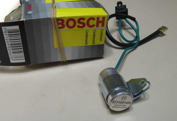
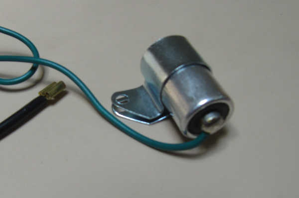
The capacitor is a Bosch 9-231-081-465, designed for use in a so-called "050" distributor. This is a common replacement distributor for four-cylinder Porsches. It likely is used in other distributors as well, as there isn't a huge difference in the internals of the distributors from those cars.
The capacitor was made in Brazil. Many Bosch ignition parts are now made there, and Brazilian part have a lower reputation than the parts once made in Germany. Still, Bosch has earned a reputation for quality, so it seemed that a Bosch cap nevertheless might be a promising option.
The capacitor is shown below. It is not large, and it probably can be adapted to fit many kinds of distributors. The measured capacitance is 0.20 microfarads, so that's certainly OK for Sprites and other British cars. Its case is made of soft aluminum, so it could not be soldered into place, as is usual in MG T-series distributors, but I would expect that modifications for mounting it would be minor.
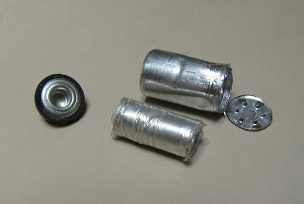
The internal structure is shown below. (The wire to the insulated connection has been removed.) The can connection consists of a ring of small, sharp bumps, which seem to make a good contact to the foil capsule. The wire connection consists of an opened cylinder, mounted and insulated by a ring of pliable rubber. The rubber provides some springiness to keep a firm contact to the capsule. The edge of the cylinder is slightly raised, so it digs into the capsule a bit. All in all, it's not everything I'd like to see, but it's not as bad as the three others, either. Indeed, the number of capacitor problems reported on Porsche forums is not nearly as great as those on British car forums, so it's probably more reliable than the parts designed for British cars. It might be a viable option.
Yet Another Option
I have become aware of another product which could solve the problem of poor capacitor quality. A seller on The Samba is offering a polypropylene capacitor, potted, in a plastic housing, with 1/4-inch spade lugs. It looks like a nice package, and it solves the mounting problem I mentioned above. As he states, the unit should never need replacement. I regret only that it isn't in a more visible place; I think it is a perfect solution to today's capacitor problems. (June, 2025 update: this ad is still on the site, but is labeled as "inactive.")