Porsche 912 Electronic Hazard Flasher
Steve
Maas
Long Beach, California, USA
March, 2011
 The
hazard flasher for a Porsche 912 is no longer available either from Porsche or
aftermarket suppliers. This seems to be a matter of great concern to the Porsche
community, but for anyone who can live without an exact replacement, there are a
few options. Mine was to make an electronic flasher.
The
hazard flasher for a Porsche 912 is no longer available either from Porsche or
aftermarket suppliers. This seems to be a matter of great concern to the Porsche
community, but for anyone who can live without an exact replacement, there are a
few options. Mine was to make an electronic flasher.
Recently I saw an electronic flasher advertised on-line for $77 US. That
seems like quite a lot of money for something that is easy to design and to
build. My flasher cost about $25, mostly using parts I had on hand. If I were
a little less selective about the relay and housing, it probably could be built
for about half that. I built the circuit on a piece of Vectorboard, a perforated board
used mainly for prototyping. In a production version, were I to go that route, a
printed-circuit board would probably be preferable.
The Flasher
The Porsche hazard flasher cannot be replaced by a simple turn-signal flasher. The hazard flasher differs from a turn-signal flasher in that it has two separate outputs to power the left and right turn-signal circuits. A turn-signal flasher would require that the left and right turn-signal circuits be connected when the hazard lights are on, but not when they are off. This would require some kind of relay arrangement, which would get complicated. Also, because of Porsche's fetish for putting switches in components' ground leads instead of their power leads, the task of creating an all-electronic version of the flasher is a lot more complicated. After an unsatisfactory all-electronic design, I decided on one using a timer driving a miniature relay.
Flasher Circuit
The flasher circuit is shown below.
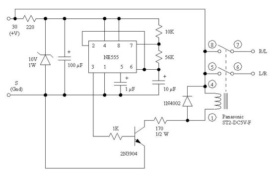
It uses an NE555 timer operated in astable mode, driving a 2N3904 switching transistor, which turns a miniature relay on and off. The relay has a 5V coil, so the 170 ohm series resistor is necessary to drop the coil voltage. The 10V zener diode is used for voltage regulation and noise reduction. The 1N4002 diode prevents transient spikes, which are generated when the relay coil is switched off, from damaging the 2N3904. It's a pretty simple circuit, and anyone even mildly familiar with analog electronic design should be able to understand it at sight.
The relay was a bit of a problem. It had to handle a minimum of about 5 amps DC, be of the DPST (double-pole, single-throw) normally off variety, and be small enough so that the circuit could be mounted in a box small enough to fit behind the pedal box. I used a Panasonic ST2-DC5V-F relay, available from Digi-Key, part no. 255-2848-ND, $12.79. This relay's contacts are rated at 8 amps, which at first seems like enough, as the bulbs require about 4.5 amps (for two, one front and one rear for each set of contacts). However, all incandescent bulbs have a high current "spike" when turned on; the 1157 bulbs I use for turn signals have only about 1 ohm of resistance at turn on. So, including a fraction of an ohm for wiring and contact resistance, we expect an initial current of ~20 amps (!!) as soon as the relay contacts close. This is less of a problem than it appears, as the contacts are closed when the current spike occurs, and it only lasts a few milliseconds. Furthermore, the greatest concern in switches is for the current when they open, and when that happens, it's only 4.5 amps. All in all, I think that the 8-amp relay should be fine; I wouldn't use a lower-rated relay. I would have preferred a relay with a 12V coil, so the 170-ohm resistor would be unnecessary, but I couldn't find one with appropriate size and contact specs.
Note that the relay coil has a polarity: the no. 4 terminal must be positive. If you hook it up backward, it won't work.
This circuit should work fine with LED lights. However, LED bulbs are probably not a good idea for the Porsche. The Porsche turn-signal bulbs are mounted vertically in the tail-light assembly, and this isn't optimum for most LED bulb replacements.
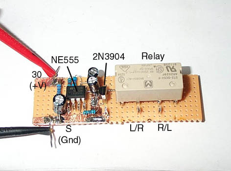
The picture below shows the circuit, built on a piece of Vectorboard, in initial tests. The 1N4002 diode is underneath the relay.
Packaging
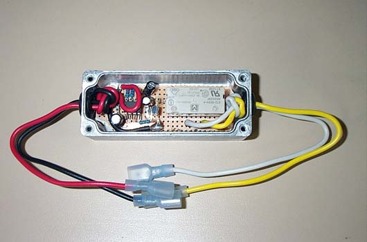
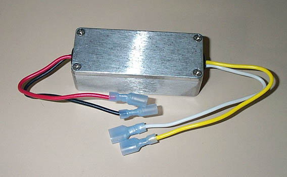
The circuit was mounted in a metal "project" box. Wire lead connections were used, with standard 1/4-inch spade terminals, to match those of the car's wiring. The red and black are the "30" (V+) and "S" (ground) terminals, respectively; the white and yellow are the "R" and "L" (interchangeable). The circuit is small enough that it could be mounted in a housing made from some 1 1/2-inch thin-wall aluminum tubing, with a couple of end caps, and that would look very much like the original flasher. As the appearance of something hidden behind the pedal box isn't of much concern to me, I didn't try that. I just tucked the whole thing behind the wiring harness, but if I wanted to mount it more securely, that certainly would be possible. One option is to use adhesive Velcro; I've done this a couple times in other cars.
Availabilty of Parts
The NE555, 2N3904, and 1N4002 are perhaps the most readily available components in existence. They are available from a number of on-line parts suppliers; I often use Electronix Express. I use the old, original, bipolar NE555, not the CMOS variant that is sometimes available. Just about any simple, silicon NPN switching transistor should work in place of the 2N3904, and any rectifier diode with an amp or so of current capability and 50V or more breakdown should do for the 1N4002. Any 10V zener diode of 0.5 watt or greater power capability should be fine, as well; zeners are often sold simply by their voltage and power specs, rather than a specific part number. I used a 1N4740, a 1W device, because I had it; the 1N758, which is half watt, would be OK too. Except for the 170 ohm resistor, all resistors are 1/4 watt (greater is OK). The capacitors are all electrolytic. The 10 uF is the only one whose value is critical; a different value will change the speed of the flashing. For other capacitors, a close value is OK. They should be rated at 25V or more. The 1 uF capacitor could be non-electrolytic, but that would probably be too big.
Testing
I ran the circuit on my test bench for an hour and monitored the temperature of the 170-ohm resistor, which dissipates close to its rated power. With a 15V supply, it stayed below 60C, a reasonable temperature for this device. I then installed the flasher in my '67 Porsche 912 and ran it for an hour with no problems. It is now installed permanently in the car. I hope I never need to use it.
Other Options: 1. An All-Electronic Flasher
The circuit below shows an all-electronic version of the flasher.
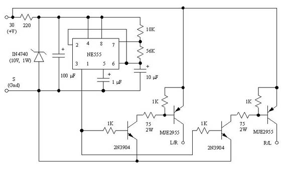
In this circuit, the relay has been replaced by high-current switching transistors. Pictures of the of the unit are shown below:
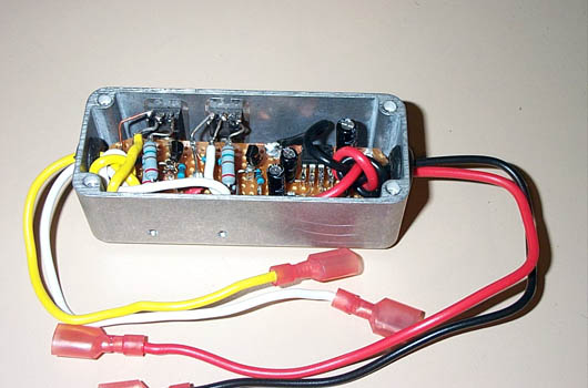
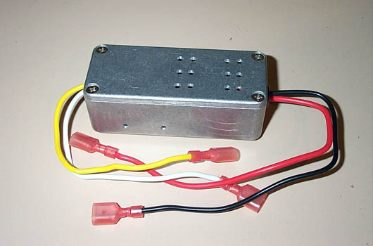
The power transistors are mounted on the side of the box to facilitate heat sinking. Conventional, thermally conductive mounting insulators for a TO-220 package must be used, as the tab must not make electrical contact to the box. Similarly, the cover has some vent holes to allow air convection. This is necessary to cool the 2-watt, 75-ohm resistors.
This circuit has two problems. First, ~ 0.8 volts are lost in the MJE2955 transistors, reducing the voltage to the lamps a bit. That's not a great problem, as the brightness is still good. A greater problem is the power dissipated by the transistors, about 4 watts (average). This is enough to heat the housing significantly, so it requires heat sinking to the mounting surface. There just isn't a place in the Porsche where it could be mounted acceptably, although it might be fine in a different car. The advantage of an all-electronic circuit is the avoidance of a relay, which has a limited lifetime.
Other Options: 2. Use of a Conventional Turn-Signal Flasher
The circuit below uses a conventional turn-signal flasher. I have not tried this circuit, but it should work.
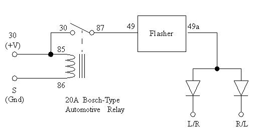
The flasher is a conventional turn-signal flasher, the type used in the Porsche. The diodes are power rectifiers, rated at a minimum of 50V and 6 amps. They will get hot, so they should be mounted in a way that allows plenty of air circulation; it's not clear to me that appropriate mounting is possible in the small area where the original flasher was located. It is possible that the lamps' turn-on surge might blow out the rectifiers; if so, rectifiers with a higher current rating will be necessary.
While the circuit is simple, it does have the disadvantage of requiring a conventional flasher. The flasher eventually will wear out and fail (but they're cheap), and the diodes will drop the lamp voltage by about 0.8 volts. Packaging this circuit is likely to be awkward.
Disclaimer
I don't like saying this, but I suppose it's necessary, now that the lawyers have taken over American society. If you choose to do this, or something similar, but don't know enough about automobiles or electricity to be comfortable with it, get some help. The consequences of wiring errors in high-current circuitry, as exists in any automobile, can be serious. In any case, I'm not forcing anyone to make one of these circuits, so if you choose to attempt it, you take full responsibility for the results. This is solely a report on my experience. It is not intended to be a set of instructions for duplicating my work or a recommendation to do it. It's entirely possible that some of the things I've done in this installation may not be consistent with existing automotive electrical standards and practices, or may even be unwise. You're on your own.