![]()
Repairing the internal engine's internal damage was, of course, essential, but the external parts had to be restored as well.
Click on any picture to see a larger version in a new window.
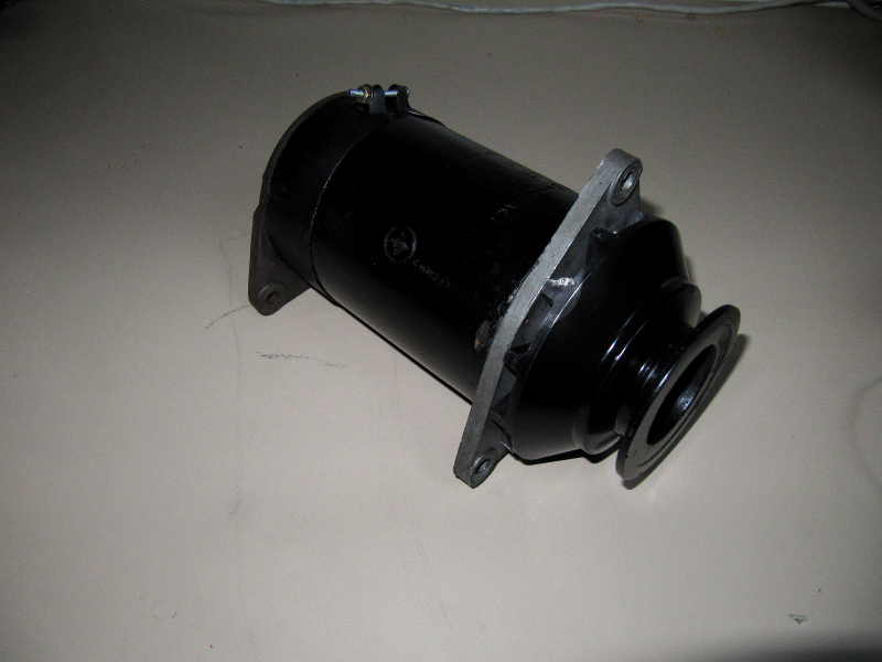
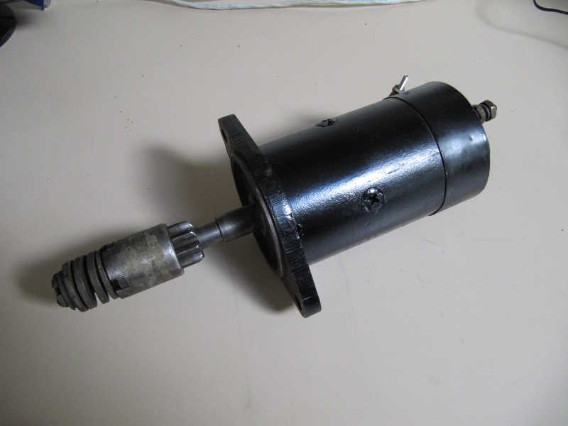
The generator worked, but it was a little beat-up looking. I disassembled it to check the brushes and other internal parts, wire-brushed off the old paint, then reassembled and repainted. Same story for the starter. For things like this, I use ordinary Rustoleum primer and gloss paint in spray cans.

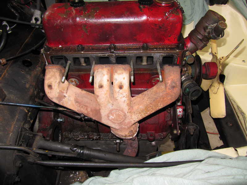
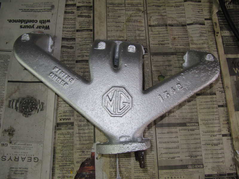
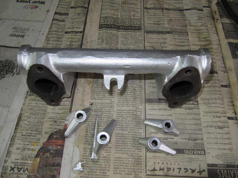
The exhaust manifold was painted with high-temperature exhaust coating from Eastwood left over from my Porsche. I used it on the intake manifold as well, and on the clamps that hold both to the engine.
I broke a stud on the exhaust manifold and had to drill it out with a carbide drill. After taking the picture below, I drilled out the other studs too, as their threads were largely rusted away. On reassembly, I used bolts to hold the exhaust pipe to the manifold.
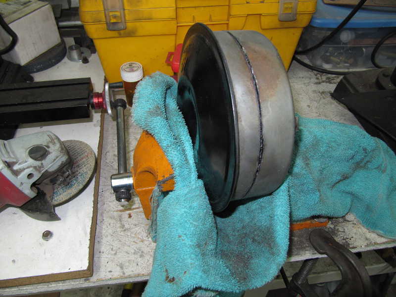
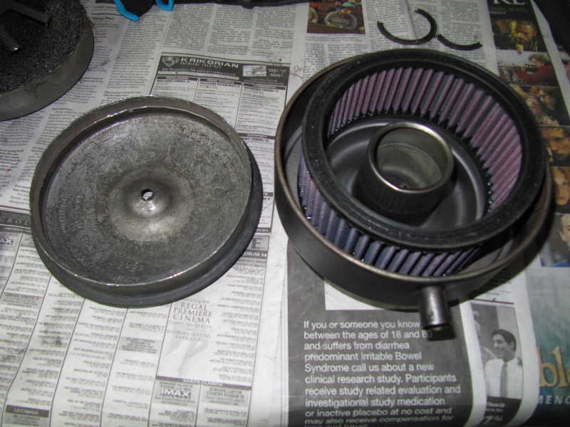
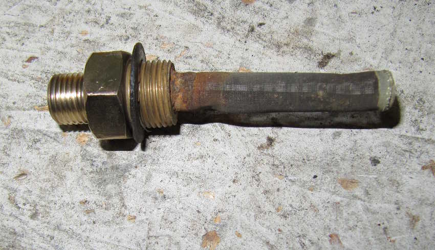
I converted the antiquated and inefficient oil-bath air filter to one using a modern filter element. I chose a K&N element, not so much because it is reusable, but it seems good quality and the manufacturer publishes sizes on-line. It is type E-9144, 2.5" high, 4.875" ID, 5.875" OD.
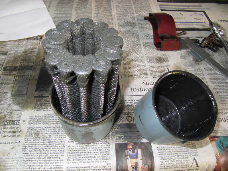
First, I cut off the part of the filter holding the wire mesh, leaving about 3/4" of metal. I did this with an angle grinder and cutting disk. The top required a little prying to get it off.
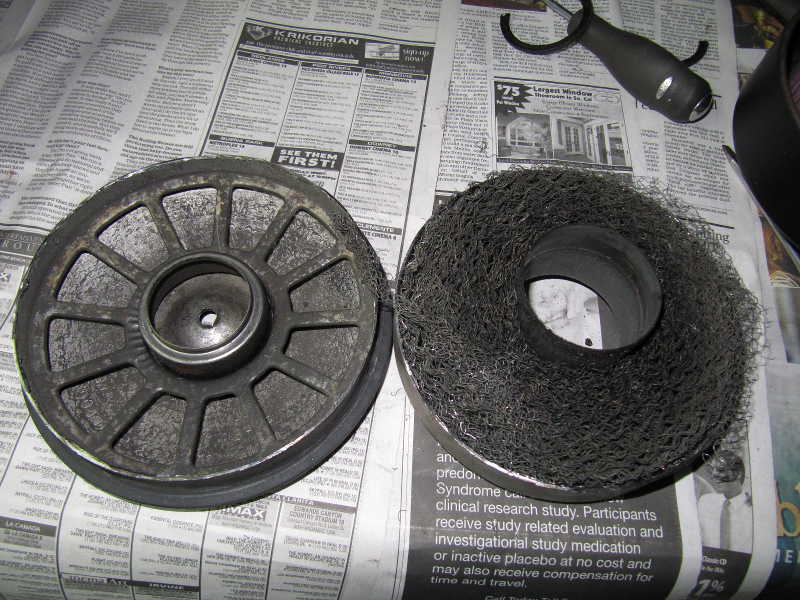
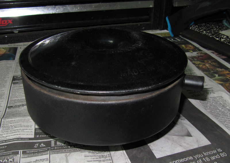
I then cleaned up the top, removing the spoke-like piece and grinding the metal edges smooth. The filter dimensions were chosen so that the top would sit at the same height as the unmodified filter. This makes it visually indistinguishable from the original unit. (I had already repainted the housing before starting this modification. The top was gloss black and the bottom flat black, a combination that seemed better in concept than it was in reality. I later repainted the base to match the top.)
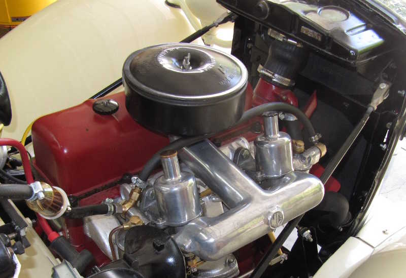
Finally, here it is on the engine.
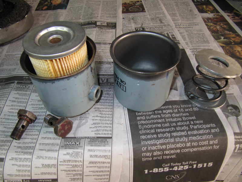
The car uses a disposable oil filter that is no longer available. It's a large, thick metal can that undoubtedly was expensive in its day. I ground off the seal and hoped to be able to clean the internal felt filter, but because of the engine damage, it was full of metal dust and couldn't be cleaned.
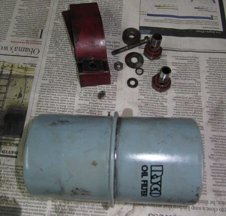
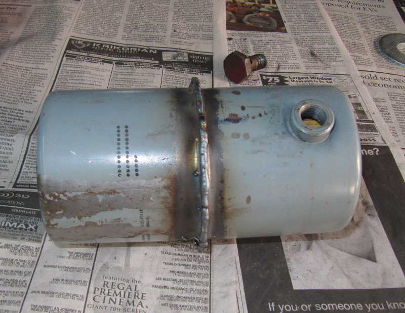
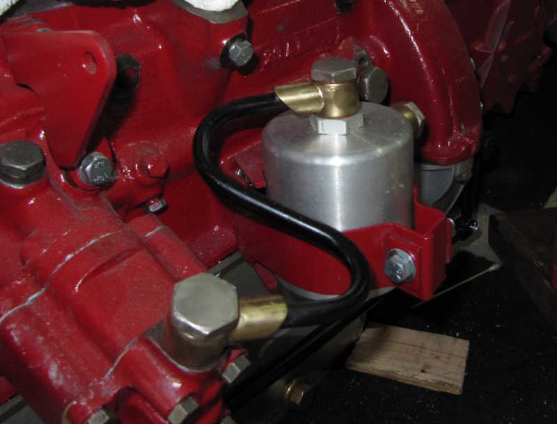
My attempt to make use of the existing filter is a good example of one of my favorite adages: the world is full of good ideas that don't work. I bought a spin-on filter, cut it apart, and mounted its cartridge in the can. I welded a spring to a pair of large washers to fill up the remaining space in the can and to hold the filter tightly in place. Finally, I welded the can together. The filter is not replaceable, but I expected it to be good for at least 6000 miles, and I could address the problem again when it needed changing. After welding, I noticed wisps of smoke that smelled like burned paper. I cut it apart again and saw that I had indeed damaged the filter. It's just as well, I guess, because I would have had to modify the oil plumbing, as the original filter's oil flow was from the inside to the outside, the reverse of modern filters. Instead, I found a spin-on adapter on eBay. Not as original looking, but much more practical.
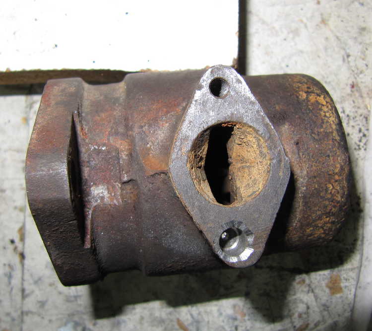
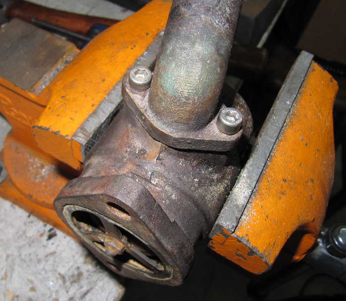
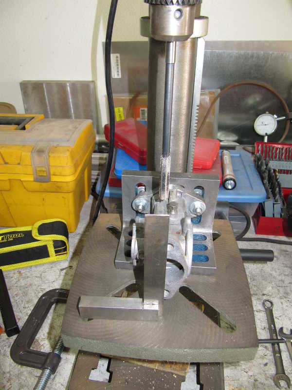
Here's an example of how I do thread repair. The screw holes in the thermostat housing were badly damaged, one worse than the other. I was able to drill out the better one and retap it for a 5 mm screw; the other, however, was not only damaged but corroded. It was almost a quarter inch in diameter, too great for a helicoil. I used the following process:
First, I drilled out the damaged area to get a clean, cylindrical hole. In this case, I had to drill it to 0.25" with a carbide-tipped drill. I chamfered the top a bit and cut a piece of 0.25" brass rod to fill the hole. I then sanded the brass piece and the hole so they were clean, for good solder adhesion, and fluxed them for soldering. It's important to use a flux that works well with steel; not all do.
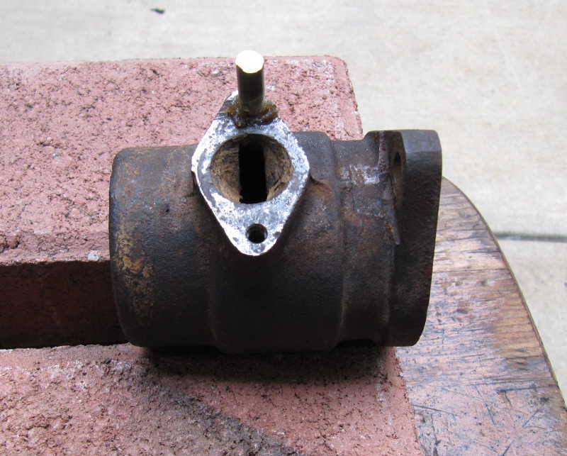
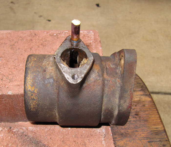
I soldered the brass plug in place with a propane torch; it's important to get the body of the thermostat housing hot enough so that the solder "sweats" down into the hole, but to avoid overheating the thermostat (which is permanently installed in the housing and thus cannot be removed). Fortunately, steel is not a great thermal conductor, so, with a little care, I was able to avoid overheating. Once the plug was soldered, I cut it off flush and filed it flat. I then laid out the hole location, drilled the hole, and tapped it for the 5 mm screw.
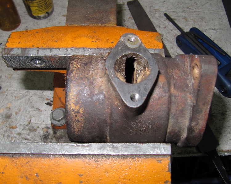
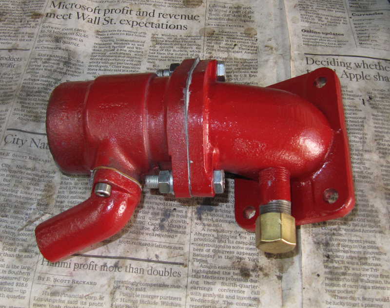
It all fit together properly. Once finished, the thermostat housing was painted and mated with the elbow. I used sealer on the joints. (I know that the bypass elbow is pointed in the wrong way. See the Radiator section to find out why.)
I've used this method many times in my bicycle restoration projects. It's easy, it can be used when the damage is great, and you don't have to shell out a bundle of cash for helicoils. Another advantage, of course, is that only hand tools are required.
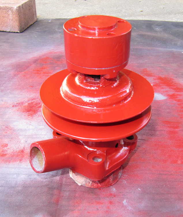
The water pump seemed to be in good condition, probably recently rebuilt. It required only clean-up and painting. That's good, because TD water pumps are expensive.
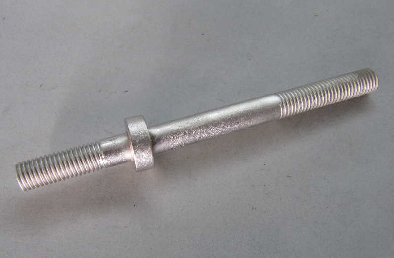
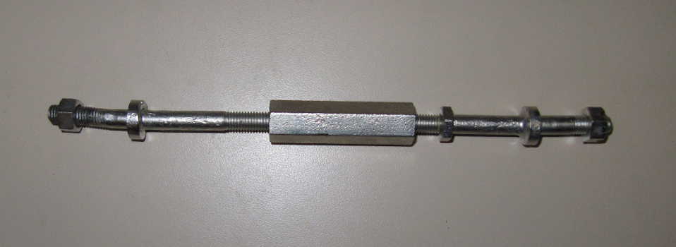
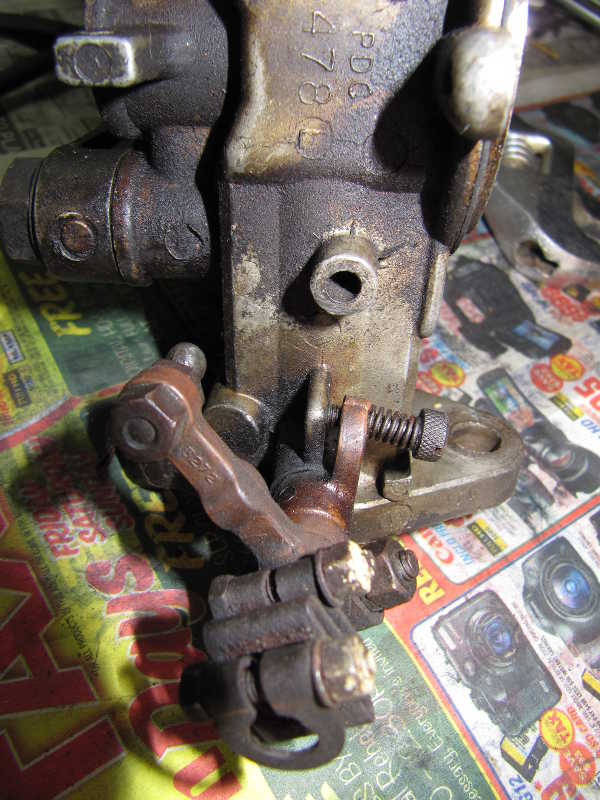
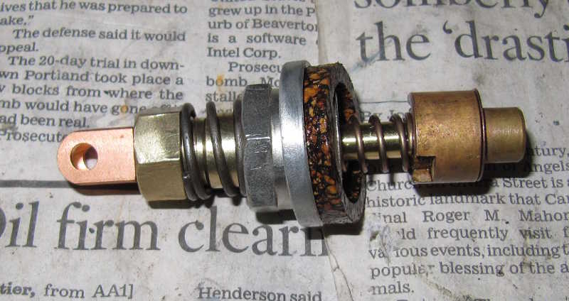
The engine stabilizer link was beat up but worth restoring; it is difficult and expensive to replace. One part had damaged threads, so I made a replacement for it on my lathe. I would have replaced the other section, but it had a left-handed BSF thread, and I doubted I'd find a die to cut one of those. Fortunately, it was in acceptable condition. I plated all the parts so they'd look a little better, and I bought new rubber bushings and metal cups.
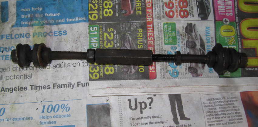
I then plated the large parts, including the castle nut. The rubber bushings were reused, and I just installed new washers. It's still a little beat up, but it nevertheless looks much better.
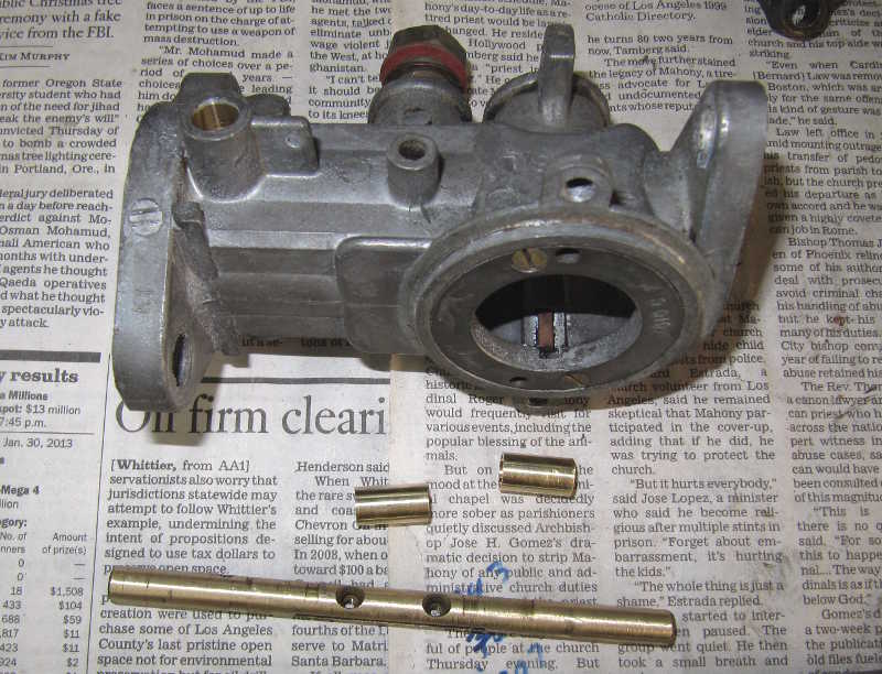
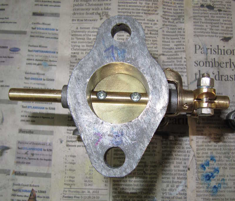
I took apart the carburetors to check their condition. They actually were not bad, but they were covered with varnish and general engine gunk. They needed cleaning and rebuilding. The throttle shafts were loose in the bodies, so those needed attention as well.
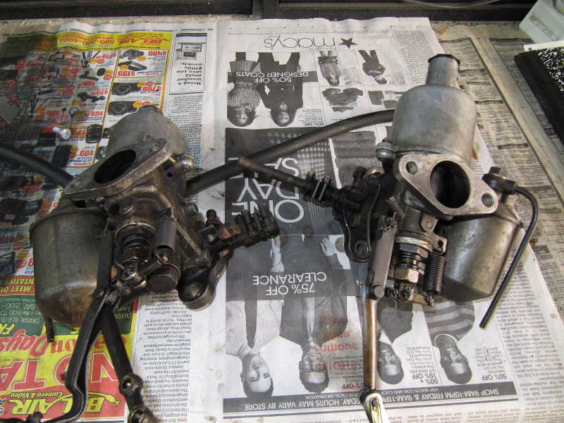
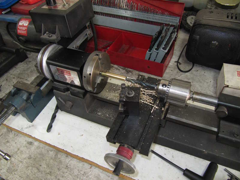
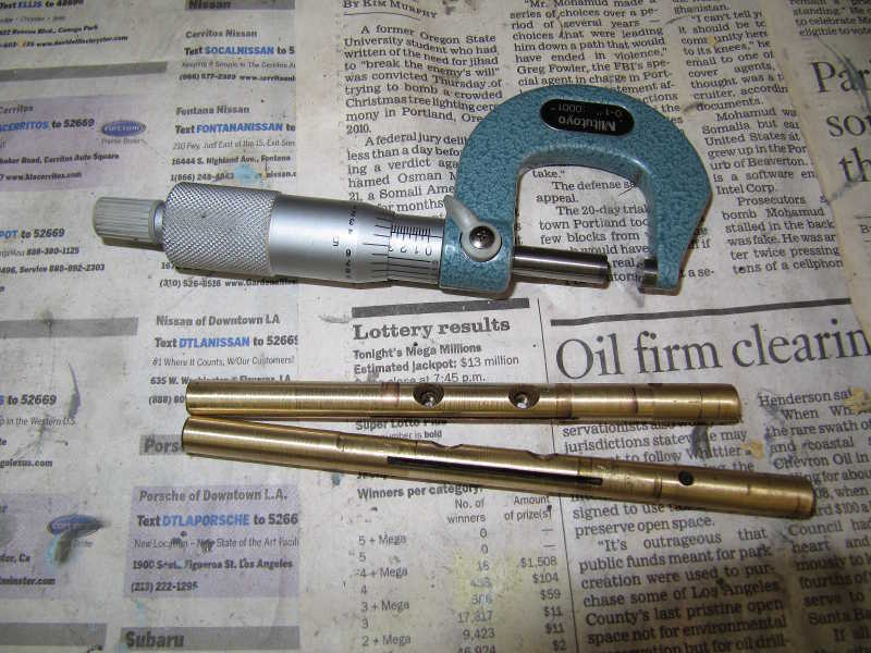
I disassembled the carbs and cleaned the parts in a 50% solution of Pine-Sol and water. This does a good job of loosening the crud so it can be scrubbed off with an old toothbrush. I then fabricated new throttle bushings and fixed the throttle shafts. In the past, I've made new shafts for SU carburetors, but it's a pain; this time, I just turned down the shafts from their original 312-mil diameter to 300, to take out the wear, and made new undersized bushings. This approach had some complications: the shafts were not perfectly straight, and the parts of the shafts where the levers sit had to remain full diameter.
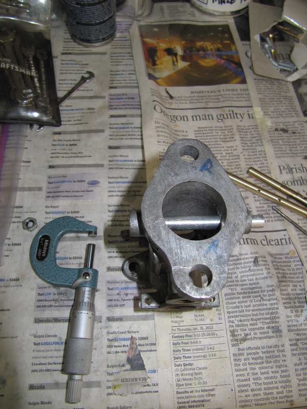
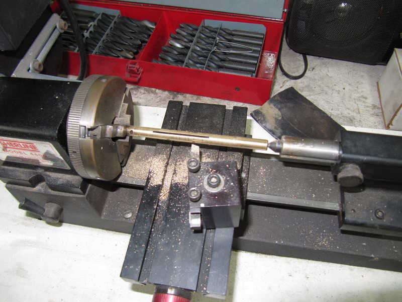
I made the bushings on my lathe, a straightforward task, but one that required high precision. I used 3/8-inch brass rod, turned down to about 370 mils to allow room for position adjustment, if necessary, and for epoxy to hold them in the carb body. I then drilled and reamed them to 300 mils ID. It was essential that the holes for the bushings be perpendicular to the axis of the throat, or the throttle plate might not close properly. To guarantee perpendicularity, I bolted the body to a right-angle plate. I used a machinist's square to set up the body in a rotational axis, lining it up with the mounting holes of the inlet flange. This alignment is less critical. I common-drilled and reamed the two holes, this time to 0.375 inches.
I made an aluminum dowel just a couple mils under the 300-mil shaft diameter to align the bushings. I glued them into the body with JB Weld, a good high-temperature, petroleum-resistant epoxy, and used the dowel to make sure that the bushings were correctly aligned.
The shafts are not perfect; you can still see some wear in them. That's not a problem, as there is plenty of full-diameter surface area inside the bushings, so there should be no significant air leakage.
I machined new pins to hold the levers in place, pressed them into the shaft, and filed off any excess.
To be sure there were no air leaks around the bushing, I let a small amount of the bushing protrude into the carb's throat and filed it flush with the throat surface. Inevitably, some of the epoxy oozed into the throat as well, and that had to be sanded off. Because of the close clearances, the filing and sanding were a little tricky.
The original screws for the throttle plate had been split and bent to hold them in place. You can do this only once with a brass screw, so I needed new ones. I found that the screws were either 5-40 UNF or, more likely, a close BA size. I had a few 5-40s, an uncommon size, in my screw stash. I machined them to the right length and cut a taper on the underside of the head, like the originals, so they would sit level with the shaft. I fitted them with loctite, after using some loctite primer on the mating surfaces. The primer is necessary for materials other than ordinary steel, and, even with steel, it improves adhesion. I polished the brass hardware and plated the steel bits so they wouldn't rust.
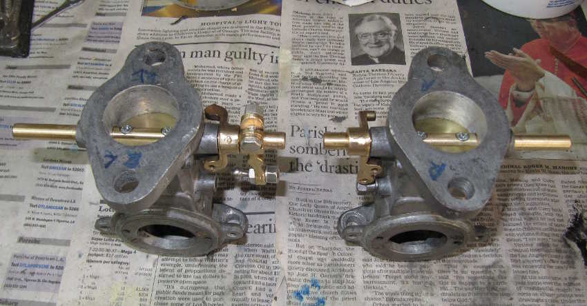
I replated the steel hardware, cleaned up the brass parts, and buffed the damper cover and float bowl. I realized that the brass would tarnish soon after installation, but it would look nice for a while. The choke linkage was installed when I fit the carbs to the engine.
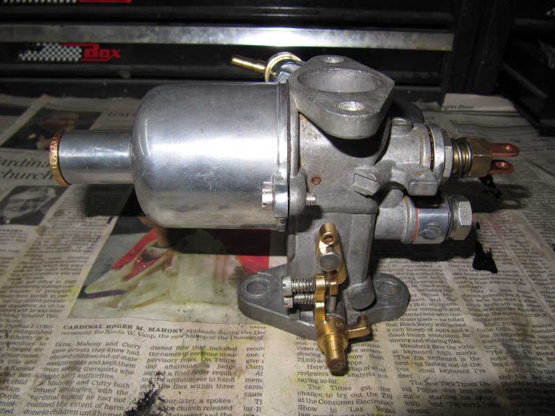
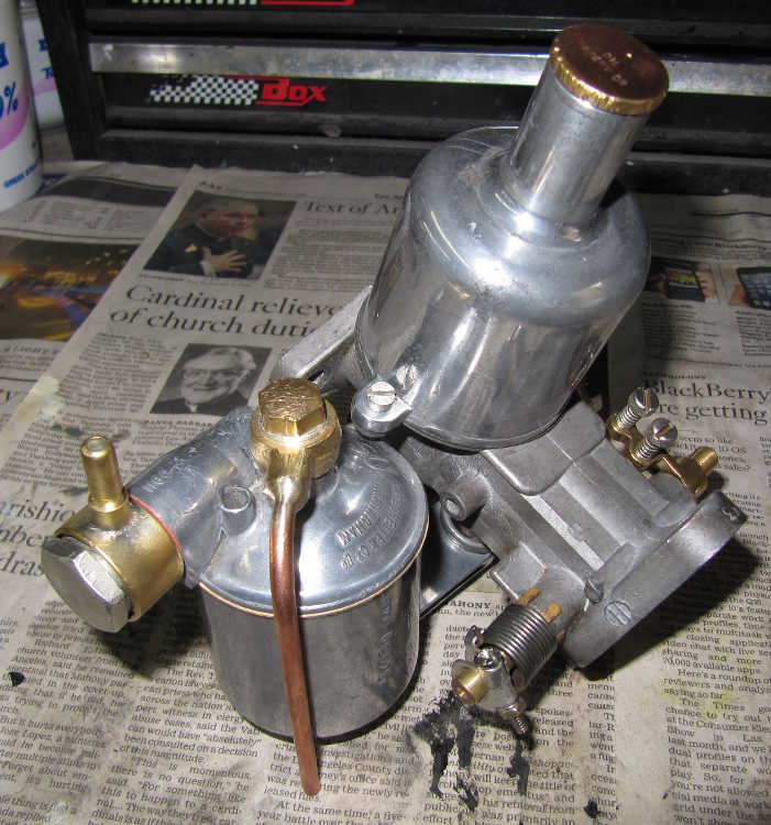
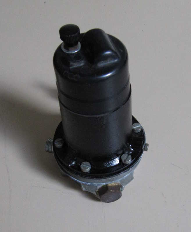
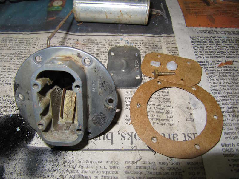
I disassembled the fuel pump to check the points and diaphragm, which were fine; the pump seemed fairly new. On reassembly, I repainted the body.
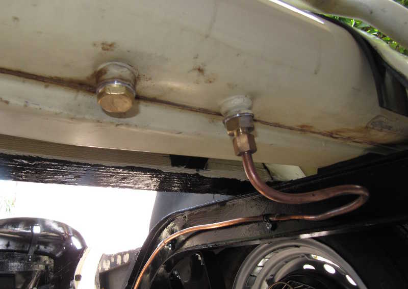
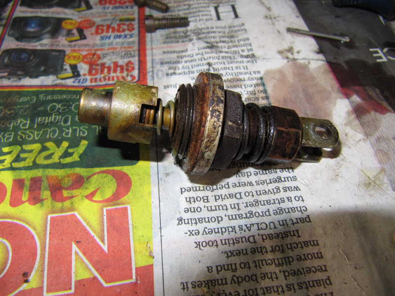
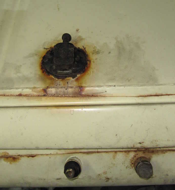
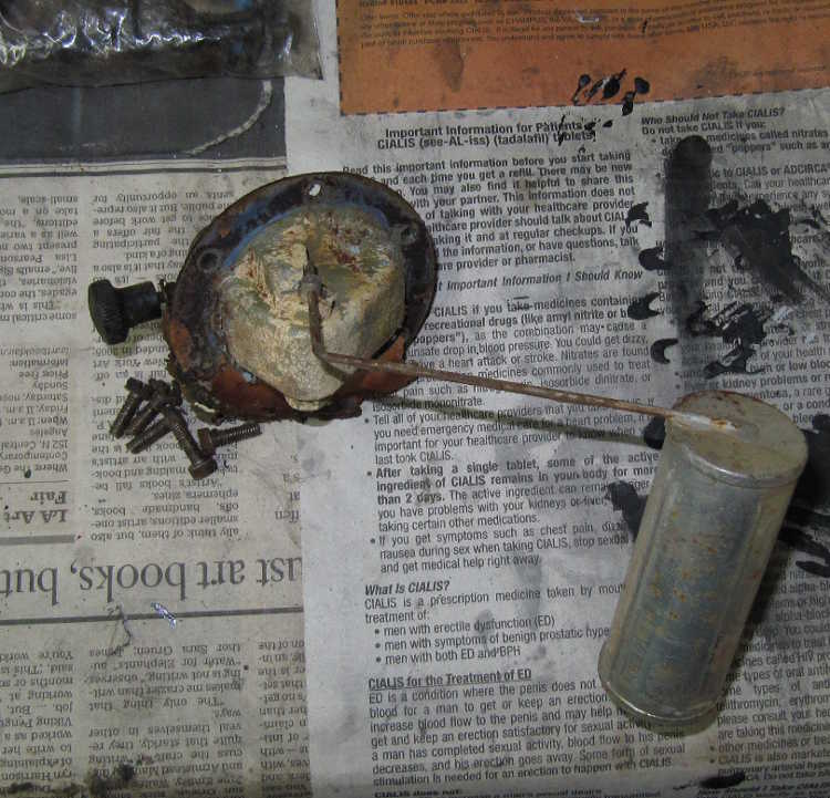
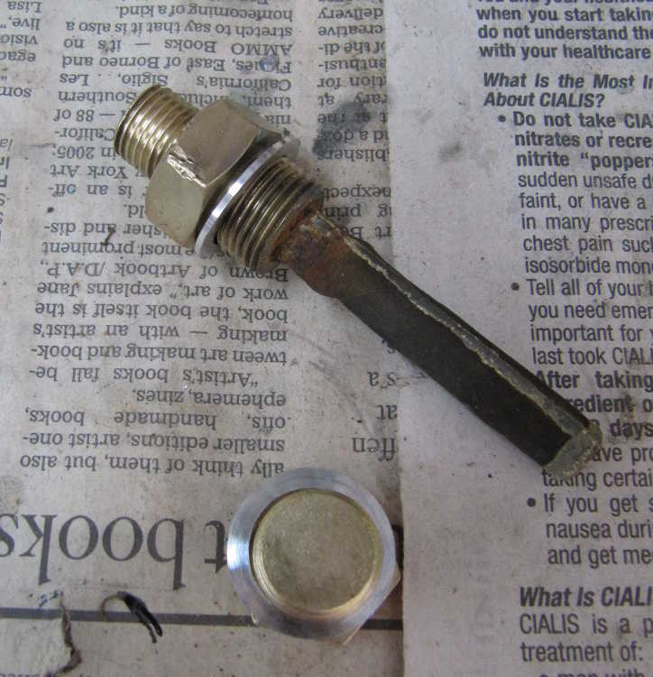
The fuel tank was in better shape than I had expected. I could see a few rust spots inside, but the galvanize coating was still good over almost all of the interior. I didn't see any need to coat it or to give it any further treatment. The low-fuel sender was in bad shape, though. It was stuck on with a lot of sealer, and when I removed it, I could see deposits all over it. I cleaned and rebuilt it, fabricating new nylon shoulder and flat washers for the electrical connection, and I replated the cover and mounting screws. I made new aluminum washers for the fuel outlet and the drain plug, polished the switch contacts, checked them for electrical continuity, made new gaskets, and reinstalled it with a sensible amount of sealer.
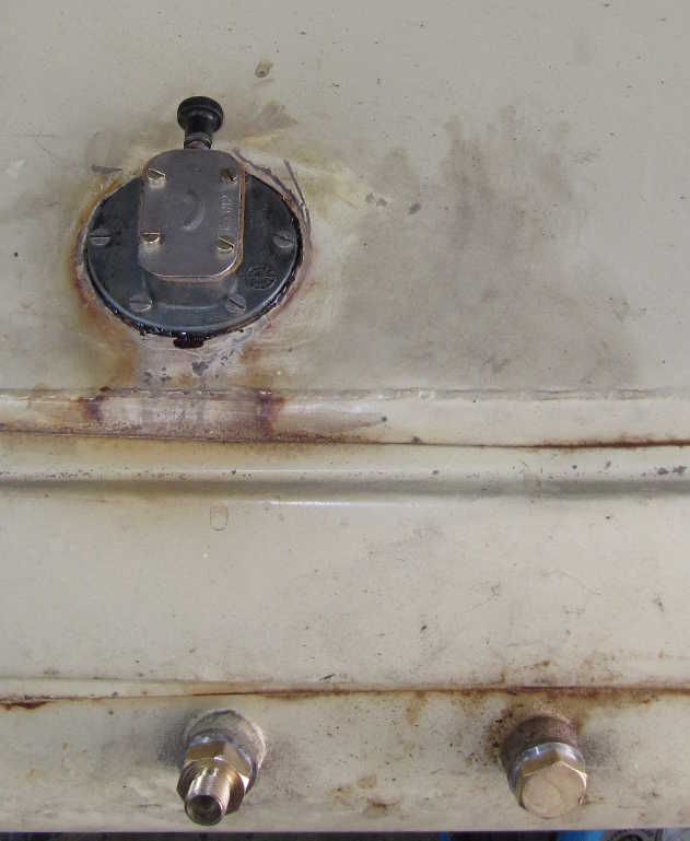
I reinstalled the tank and hooked it to the fuel line.