Circuit Gallery
Here are some circuits we have developed over the years. Many of these are "firsts;" all are at least interesting. Unfortunately, the most impressive circuits have been proprietary work for clients, so I can't post it here. Still, that makes a point, I think.
Broadband, 18-40 GHz Mixer
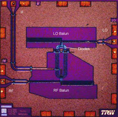
This mixer uses an unusual set of baluns. Both the RF and LO use asymmetrical Marchand baluns, but the RF has an additional section that is used for IF extraction. The mixer exhibited between 7 and 8 dB conversion loss from 18-40 GHz and had a dc-11 GHz IF bandwidth.
This circuit was published in the 1998 IEEE MTS Symposium.
Spiral-Balun Mixer
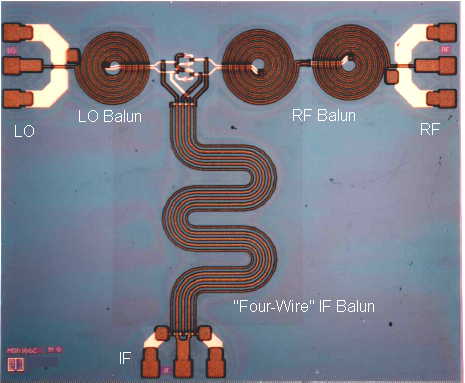
This might well be the strangest mixer IC you've ever seen. The RF and LO baluns are bifilar spirals, good for about 3-12 GHz. The squiggly thing is a planar realization of the four-wire balun (it uses five wires, actually). The long lines made this mixer a little lossy, about 9 dB conversion loss, but the bandwidth is as great as anything ever achieved in an IC. The IF, for example, was good for 0.5-14 GHz.
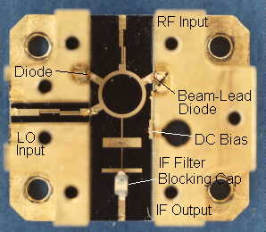
26-40 GHz Star Mixer
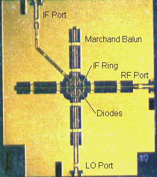
This monolithic circuit covers 26-40 GHz with a dc-12 GHz IF. Our latest versions of this circuit cover 22-40 GHz with a dc-18 GHz IF. This mixer exhibits conversion loss of 5-6 dB with very little ripple, and output IP3 of better than 16 dB over most of the band. RF-to-LO isolation is 30-50 dB. And so on. We have designed dozens of similar mixers in other frequency ranges with similar performance.
The photo makes the RF and LO baluns look asymmetrical, but in fact they are identical.
The World's First MW FET Resistive Mixer
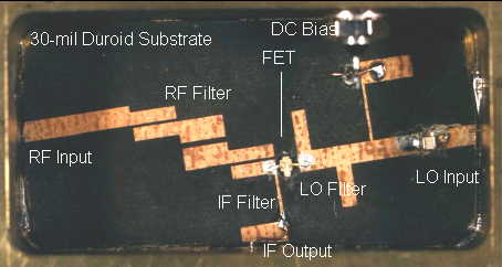
Ugly as this may be, in its unplated brass housing and Duroid substrate, it's the first one, and it worked well. This mixer had 27 dBm output IP3 at X band, with only 11 dBm LO power. The output 1-dB compression point was 15 dBm and conversion loss was about 6 dB.
45 GHz Active HEMT Mixer
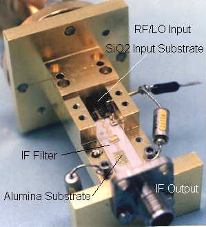
Developed in 1984, this was the first millimeter-wave active mixer ever produced and the first active HEMT mixer. It used one of the first TRW HEMTs. It had about 3 GHz RF bandwidth and 1.5 dB conversion gain, and the SSB noise figure was roughly 6 dB. We took the unusual step of using different substrates for the input and output; the input is fused silica, and the output substrate is alumina. The mixer uses an antipodal fin-line waveguide-to-microstrip transition designed by Mike Sholley; to save development time, I also swiped one of the test fixtures for his 45-GHz amplifiers.
This circuit was reported at the 1985 European Microwave Conference.
60-GHz Diode Mixer with Loss Below 3 dB
This is an image-enhanced 60 GHz mixer with a minimum conversion loss of 2.8 dB. As far as we know, it was the lowest conversion loss ever achieved in a millimeter-wave mixer. It uses a whisker-contacted, dot-matrix diode. This is early 80's technology, thoroughly obsolete today, but, boy, was it fun to work on!
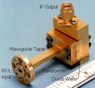
30-GHz Balanced Mixer
This singly balanced diode mixer was developed for the Advanced Communication Technology Satellite (ACTS). It operates at 30 GHz with 2.5 GHz bandwidth and a 4-GHz IF. Conversion loss is a flat 6 dB over the RF band, at fixed IF. The diodes are Alpha GaAs beam-lead devices. The mixer is approximately 1.5 cm square.
The substrate is 250-um fused silica (quartz). It looks black because the quartz is transparent, and you are looking at the back of the ground plane's adhesion layer.
The World's First MESFET MW Multiplier
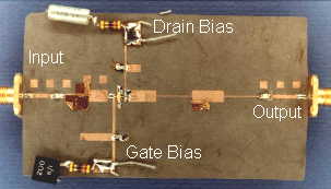
This circuit has a strange history. My Ph.D. dissertation was on FET mixers. Around 1982 I realized that the LO analysis (which was just a type of harmonic-balance analysis) could be modified for FET multipliers and amplifiers. I experimented a bit and realized that it would be possible to get about 10 dBm and unity conversion gain in a FET doubler--ideal for mixer LOs! I built this circuit in a hurry, using mylar tape as a resist. It worked just as it was supposed to.
I never published this circuit; I'm not sure why not.